Gibson Les Paul Studio Shred Rebuild

 ThePatient

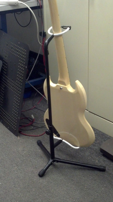
I am a sucker for projects.  And I’m a sucker for Gibson guitars.  So I saw this black Les Paul at a local guitar store, looked at the price tag, and asked what was wrong with it.  Broken headstock?

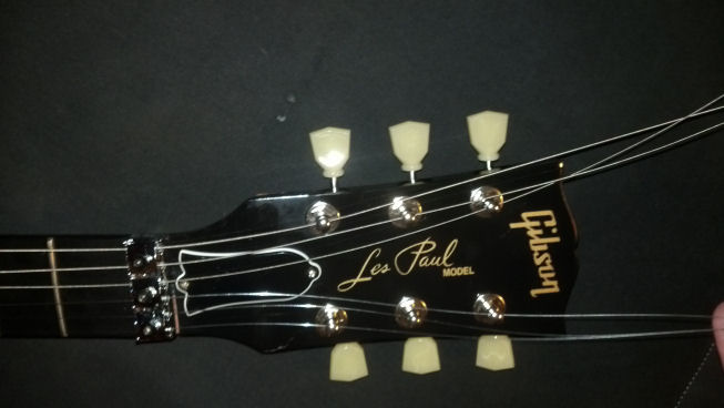
This 2012 Gibson Les Paul Studio Shred, sporting a Floyd Rose tremolo system, has a mahogany neck and headstock.  The body is a glued sandwich of maple and mahogany.  Mahogany is a wonderful tone wood with a fine and even grain. However, mahogany is, in my opinion, more fragile than other hard woods. My guess is, this Les Paul was dropped in transit (UPS/Universal Package Smashers strike again!) and the headstock, which is often unsupported in even the high-end graphite guitar cases, snapped when it hit the ground string-side down.

Well, I talked to my bride, who amazingly consented to my newest guitar.  This would be my birthday/anniversary/Christmas gift for the this year.  And the next year.  And the year after that.

The staff at the local guitar store said that they could get me the truss rod tool, original hard shell case, registration paperwork (this was a BRAND NEW guitar!) and get me out the door, incredibly cheaply for a Les Paul.  No doubt the store also received a settlement on the freight-damaged guitar, but I digress…

I couldn’t pass it up and quickly took it to the shop.

Damage assessment proceeded with blocking the Floyd Rose tremolo, stripping off the strings, pulling off the locking nut, removing the tuning machines, and taking a look at where we were.

FrontDeformation

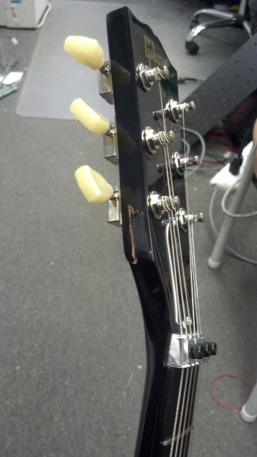
Amazingly, the veneer over the tuning head, with the Gibson logo, was bent but undamaged!

 OriginalBreak1

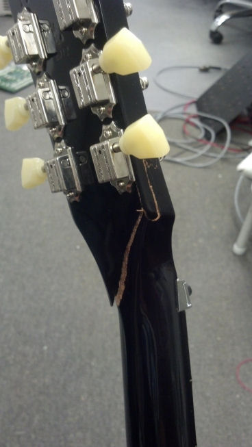
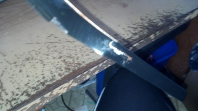
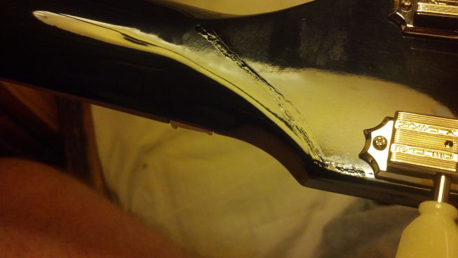
The break was clean, for the most part, with just a little damage to the finish of the guitar.  However, to get the adhesive repair all the way into the furthest extents of the break would take some thought.

OriginalBreak2

Other areas of the guitar were damaged in the ‘accident,’ and would require some touch-up to the nitro finish.  This could be done on a small scale, with a touch-up pen.  I’d cross that ‘bridge’ when we got there.

My plan was to glue and clamp the broken headstock back onto the neck without separating the two parts and damaging the veneer on the face of the headstock.

OriginalBreak3

As mahogany is a porous wood, I would avoid using epoxy, because the components that make up the mix might penetrate into the wood at uneven rates, potentially compromising the strength of the final bond.  On the other hand, the tension of the strings would tend to pull the joint apart, so I thought that a repair like this would stretch the limits of adhesive chemistry.  Luckily, the locking nut arrangement would keep the tension on the playable portion of the strings, while the remaining string running up to the tuning machine could be entirely slackened after the guitar was tuned and the nut tightened.  Further, I was assured that Tite-Bond glue would create a finished repair that was stronger than the wood surrounding the joint.

ClampPrep

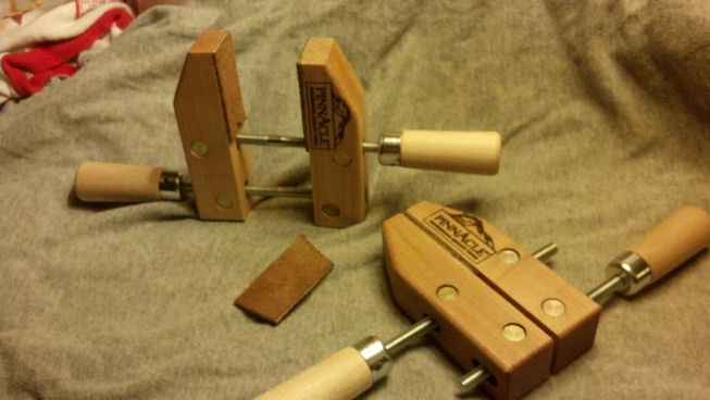
I prepared the jaws of my wood clamps with leather.  This is something that I intended to do for a long time, but protecting the fresh nitro-cellulose finish on this guitar motivated me to “git-er-done!”

ALittleGlue

I poured a little Tite-Bond into a non-porous mixing container.

ALittleWater

A little distilled water would thin the wood glue to get it down into the small cracks up against the veneer face of the headstock.

TrialClamp1

Here, I was doing a literal ‘dry run’ to see how the clamps would work.

TrialClamp2
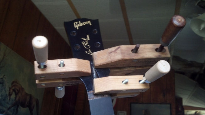
Three clamps may be the way to go here.

FirstGlue1

Sorry about the blur, but I’m holding the guitar vertically while the thinned Tite-Bond runs down into the recesses of the break.

FirstGlue2Again, things are a little ad hoc while running the thin glue where it needs to go.

BigSquish
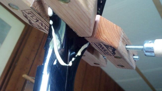
The rest of the crack is painted with straight Tite-Bond and squeezed as shown here to blow all the air out of the crack. We’re just doing this once!

ClosedCrack

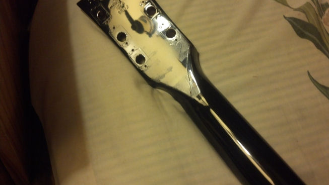
The neck, about 24 hours later.  The finish needs to be buffed to remove the marks from the clamps, but the crack is closed with no chipping.

FinishOptions

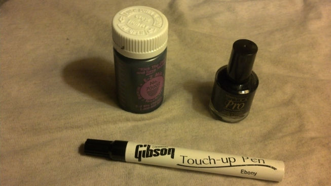
There are three choices for paint touch-up. One is polyurethane automotive touch-up paint, black nail polish, and the right tool for a Gibson nitro finish, e.g. the paint pen.

NeckTouchupBest shot of the Gibson paint pen in action.

NeckPostTouchupThis is the repainted areas before machine buffing.

TremoloCoverCrackMore carnage from the original accident. The tremolo string cover is snapped in half.

TremoloCoverPreTouchupNote the damage to the finish where the impact broke the tremolo spring cover.

TremoloCoverPostTouchupOnce the new cover is installed, this finish damage will be hidden.

NutGroundHere’s a little guitar tech porn. The locking nut is grounded to the rest of the guitar using a flat sheet of copper-plated Kapton tape, rather than a discrete wire;

Nut1More Guitar Tech Porn!

TrussWasherThe washer under the truss rod nut.

TrussNut
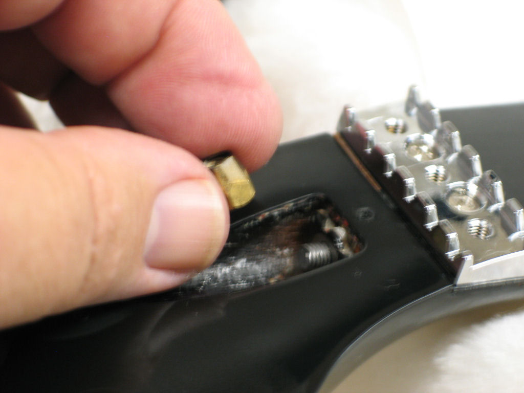
And the all-important truss rod nut.

TrussWrench
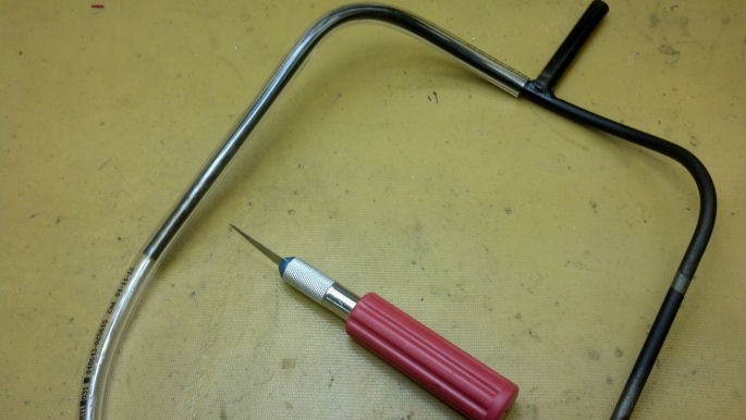
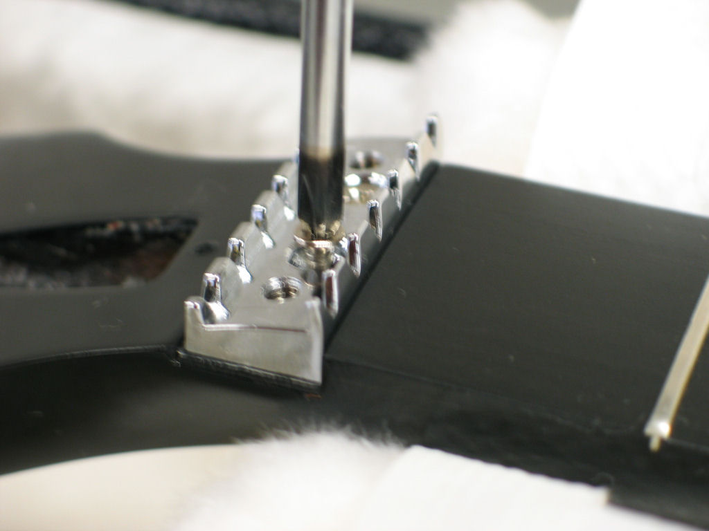
Here is a close-up of the factory Gibson truss rod adjustment tool.

NeckBuffoutHere you can see that the finished repair is not perfect but a little finish irregularity is all that is left of our broken headstock.

StringUp1More tech porn. These tuners are not lockers but I’m in the habit of stringing a guitar string through the tuner, then pulling back enough string to get the wrap I want around the post.

TremoloBlockRecognize my Floyd Rose Tremolo block? It’s a nine volt battery covered in a layer of heat shrink tubing.  The covered battery is ‘close enough’ to get the tremolo level on the arched-top Les Paul.

TremoloBlocked
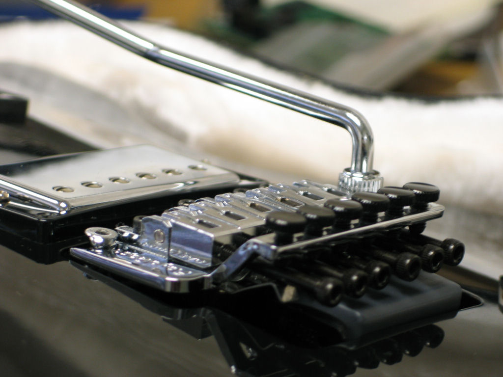
The tremolo block at work.

StringUp2More tech porn. This Floyd Rose was probably built in South Korea.  I may investigate whether the European version is a little ‘tighter’ because the tremolo bar can rattle in the socket, making a clicking noise while working the tremolo.  Probably not what was intended…TremoloCoverTape

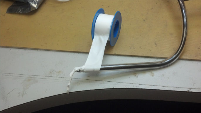
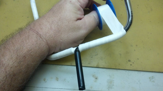
Here, a new tremolo cover is fabricated. I used a smoke/translucent cover to show off the springs and tremolo block. Yeah, I’m a geek.  The tape will protect the finish of the new cover.

Tape1
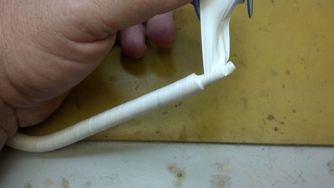
Here is my plexiglass ‘mummy’ ready for the edge trimmer.  Once the outline is established, holes will be drilled and countersunk, and the edges will be flame-polished.

StringUp3Even non-guitarists like this pic. Rock and Roll!

Gibson GA-30 Amp Refurb

NewHandleMy father found this amp in a pawn shop in Enid, Oklahoma around 1969.  A high school buddy and I had a guitar duet act, and to support us, he was renting Kustom amplifiers to use as PA systems for our gigs.  I think my father purchased this amp as a way to cut his rental expenses.  The amp worked, and it served me well throughout my high school years.  Unfortunately, I knew nothing of its background and really didn’t appreciate the bit of guitar history it represented until I pulled it out of the closet last year to try it out again.

Before my father purchased this amp, someone had removed the smaller loudspeaker and replaced the larger Jensen loudspeaker with a similar Utah unit, and had changed the output transformer. Perhaps we can update the amp, get it working, and return it to a configuration similar to the way it was Back In The Good Old Days. Well, let’s get to work!

OldHandleThe leather handle was not original. This item was sold as a repair handle for luggage. And now it too was broken.

OldHandleHardware

This bracket used to have a center post that passed through a slot in the original leather handle. The original rivets were weak and were easily removed from the amplifier cabinet.  As a replacement, I ordered a Fender amp handle and hardware (yeah, call me blasphemous, but the flat Fender leather strap is probably closer to what originally shipped on this cabinet than anything you have mounted on your relic Gibson amp.)

FirstLook1I removed the amplifier’s chassis and put it on the bench. We’ll get back to this in a moment.

OldBaffleThe cabinet was disassembled as well.  The old baffle was crudely cut from half-inch-thick particleboard to mount the single Utah loudspeaker. Just after this picture was taken, it crumbled into several pieces and discarded, a victim of age and humidity. A new one would be fabricated from baltic birch plywood to accommodate the second smaller loudspeaker, as an acknowledgement of the original configuration of this amplifier.

New8inchThanks to eBay, I found the eight inch loudspeaker to match the larger twelve-inch loudspeaker already installed in the amp. I just love NOS (New Old Stuff!)  I had agonized over re-using the big Utah loudspeaker or moving back to the Jensen loudspeakers, but the agony was soon ended when I balanced the checkbook. These Utah loudspeakers will be fine for now, as I really wanted this amp as a daily player and not a museum piece.

NewBaffleStartI sketched out the location of the loudspeakers with respect to each other and with respect to the amp enclosure on the piece of baltic birch plywood. Here you can see the starting holes from which the orbital jigsaw will start through the plywood. I do have the router and the circle template, but I opted for the jigsaw to keep the mess to a minimum as bad weather kept this work inside the office.

NewBaffleFirstHoleOne down!

NewBaffleRoutedAndTrimmedBoth loudspeaker holes done and rounded over to minimize edge diffraction. The plywood was also trimmed to fit in the amplifier cabinet.

NewBaffleSealI applied several coats of wood hardener. This stuff soaks into the wood, sealing and strengthening it. The resulting baffle is as rigid and stiff as I can possibly make it. Note – try this wood hardener treatment on old guitar amp cabinets that have become ‘weak’ over time. You might be pleased with the improvement.  The baffle was then painted with a semi-flat black paint on the front side.

TeeNutsThe loudspeakers themselves would be bolted to the baffle using these tee nuts, which were also painted black so that they would not be visible through the grille cloth.

LoudspeakersInstalledHere’s the cabinet so far. Loudspeakers are bolted to the baffle, and the baffle is bolted to the original amplifier cabinet. Only the front (grille) side of the baffle is painted black; you are looking at the sealed but unpainted side.

ChassisNeedsCleaned1The chassis was obviously dirty. Note the clouded tube. This is an indication that the glass envelope of the tube has been compromised and moisture has ‘gotten’ the ‘getter,’ the region at the top of the tube that is usually silver in appearance. We will pull the tubes and check them, but I don’t have really high hopes that we will find many good tubes here.

ChassisCleaned1Here I’ve cleaned the painted chassis with leather cleaner and conditioner, the same stuff that you would use on work boots. It not only cleans well, but does a good job of preserving and restoring the brown paint with which the chassis was painted.  Good stuff!

ChassisCleaned2The top of the chassis is squared away using the leather cleaner. Oh, and all the tubes were trash. But checking the tube layout against the schematics available from Gibson, I discover that this was probably an ‘interim’ model, between the GA-25 and the GA-30. The circuitry is the GA-25 circuit, built with discrete triodes for the phase splitter, and using the four-input circuit of the GA-30 amplifier on a chassis marked GA-30, That information places the date of manufacture of this amplifier chassis around 1949, Fresh NOS tubes are on order from my vendor.

OriginalCaps1Flipping the chassis over, we see the power supply choke on the left side of the chassis. One of the output tube sockets is nearest the observer, and the high voltage caps is the yellow units visible to the right of the picture. The high-pot test on the choke shows that it’s good to over 400 volts.

OriginalCaps2Shifting our gaze to the middle of the chassis, we see some of the black capacitors which are interstage coupling capacitors.

OriginalCaps3Moving to the right, we see the other high voltage filter capacitor and the rest of the interstage coupling caps. These will all be changed out with modern components. As I mentioned earlier, I wanted this amp as a player, not a museum piece. Some collectors will retain the appearance of their chassis by reusing the package of the original component. The wax and internal structure of the capacitor would be removed, a modern component placed inside the package, and the ends resealed with the original wax. Maybe this is important to some people, but this amp has already been worked on, and I want it to play it, not look at it.

NewCapTeflonHere I am covering the component lead of this new interstage coupling capacitor with Teflon tubing. If this style of construction is good enough for America’s Space Program, it’s good enough for me.

NewCapsThe blue electrolytic capacitors are the new high voltage filter caps, and the small white cylinders are the new interstage coupling capacitors. At the top if the picture, you can see a gray wire leading away from the terminal strip towards the center of the chassis. This carries a sample of the output signal back to the preamplifier tubes, implementing a form of negative feedback to the amplifier. This appears to be an aftermarket modification. I left the circuitry in place but left the option to remove the sample tap at the loudspeaker if I don’t like the sound of the negative feedback added to the circuit. This is a guitar amplifier, not a hi-fi.

OPXFMR1The insulation on the output transformer crumbled. This has been worked-on before, and I don’t have the ‘correct’ cotton sleeving used on old electronics like this… nor do I wish to use it here.

OPXFMR2New PVC insulation was slipped over the lead of the output transformer and more wire was soldered to the output transformer lead,  Heat shrink tubing is employed to protect everything. The black thing on the right side of the pic is the nozzle of my hot air rework pencil, perfect for shrinking tubing.

RectifierCheckThis is the first power check. Only the rectifier tube has been installed. The voltages for filaments, high voltage, and bias points all check OK.

PreAndPhaseSplitterCheckThe input circuit is now driving the phase splitter tubes, but the final amplifier tubes are omitted for testing. This allows everything to be checked at ‘no-power’ levels but with realistic loads on the power supplies.

SwitchDisassembledOne issue I found was that the slide switch labelled “Tone Expander” was dirty and intermittent. This switch was disassembled, cleaned, and reassembled. Not a job for the faint of heart.

OriginalLineCordThe power cord was in excellent shape, which meant I probably replaced it back in the 1960s and forgot about it. When I rebuilt the amp, I thought that it was low-risk to leave the two-wire cord in place as there were no ‘death caps’ across the AC line as are found in some Fender amps. However, the chassis was ungrounded except through the metal parts of the electric guitar and thus hum appeared.

New3WireCordSo I installed the meanest, nasty-est, biggest, baddest three-wire cord set that I could find in place of the original line cord.

New3WireCordInstallNow that the shape of the plug established which conductor was hot and which one was neutral, I changed the wiring so that the fuse holder and ON/OFF switch was now in series with the hot (black) wire in the power cord. The green wire safety ground got its own lug at the star grounding point seen in this picture.

InitialTestOne final test before final assembly. A microphone is used to check for hum and low-level signals. Later, a signal generator will replace the microphone and a resistive load will be used in place of the loudspeakers to verify that the output transformer is up to the job of driving four ohms. Output tube operating point will be verified. We are not far from Rock-n-Roll Land now!

WireDressThe loudspeakers and chassis are placed in the guitar amplifier cabinet. The output transformer interferes with the frame of the larger loudspeaker, so it was moved to a place of honor on the baffle. Some sane and rational wire dress keeps things under control, or at least that’s the plan.

TubesInstalledHere are all the tubes. All that remains is to reinstall the back panel and final checkout. This is one of my favorite pictures.

RockinBedroomGo Time!

Teflon Coated Guitar Stand

Front

A few guitar brands, Gibson, for instance, uses nitrocellulose lacquer to finish their guitars. This finish may be easily marred by just touching other objects, particularly when the finish is less than a year old.  In this project, I wanted to explore alternatives to surgical tubing used on inexpensive guitar stands, with an eye towards protecting nitro finishes. NOTE – Special thanks to the local band “Jealous Creatures” who donated this stand to The Unbroken String Crew.

RawTubingThe old surgical tubing that originally protected the guitar from the metal parts of the guitar stand was already gone, so some quarter-inch vinyl tubing would be a good cushion over the bare metal. For most guitar finishes, you could just use this tubing and call it done, but I wanted a layer of something really inert in contact with the guitar.

CutHereHere, the vinyl tubing is cut to length. The plastic end caps would be reused in this project, and the vinyl was cut to length to accommodate them.

TopBracketThis is the support for the neck of the guitar, with the vinyl tubing.

TubingBottomHere, we’re covering the bottom support with the vinyl tubing.

GettingStartedThis is a roll of one-inch-wide Teflon plumbers tape, As you can see, I’ve begun covering the vinyl with the tape. There is no adhesive on the tape, only pure Teflon, so those black end caps will hold the beginning and ending ends of the tape in place when we’re done.

WrappingEach layer of tape overlaps half of the previous layer.

KeepWrappingCrossing over the half-way point, you can see that I just jumped across the bar in the center and continued covering the vinyl tubing with Teflon.


AtTheEnd

The other end of the Teflon tape is wrapped all the way to the end.

FirstCapThe little black end cap covers the loose end of Teflon.

BottomWrappedThe bottom support is finished.  The top support that goes around the neck of the guitar is covered in a similar manner.

BurnishTeflonNext to the black cap, you can see the overlap in the Teflon tape. To finish the job, I used my fingernail to smooth out the wraps of Teflon. The wraps disappear and the Teflon appears to be painted onto the stand. It’s a little harder to see, but the Teflon wraps near my fingers have been burnished and the wraps disappear.

FinishedStand
The finished product.

This project is not intended to be the last word on protecting nitro finishes, but rather is to encourage luthiers and guitar enthusiasts to think outside the box. There is a school of thought that damage to nitro finishes is caused solely by the mechanical pressure on the soft finish, and that this damage can be polished or buffed away. In other cases, some discoloration may occur when the guitar is stored next to leather straps or other sources of chemical impurities, and this damage cannot be repaired without refinishing.

Back
Who would risk damaging the finish on this 1968 Gibson SG Junior in Arctic White? Not this fat boy!