
The problems with which this amp suffers are the Bread and Butter for electronic service guys. Broken power switches and broken input jacks are common in so much gear these days. Let’s get to work!
 The original power switch was just “plum wore out.” This was a mechanical problem, not so much an electrical problem. The contacts were intermittent due to metal fatigue of the components inside the switch and the decay of the plastic used to manufacture the switch. Out it goes!
The plastic body of the input jack was shredded as well, a victim of time and use. Funny thing is, Fender continues to use this style of plastic bodied jack on their higher-end amps, which I have considered to be a real weakness, particularly to anyone who uses their gear to earn a living.

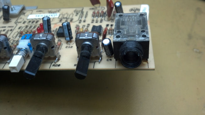
My strategy was to replace the plastic input jack with a steel Switchcraft unit that bolted to the front panel, then wire from the terminals on the jack to the proper circuit board pads. Here I have marked which PCB terminals were tip (T) and ring (R).

The rest of the circuit board was in good shape, with no signs of damage. The hybrid output amp module (barely visible at the top of the picture) had already been replaced and was still operational.

But I’m sure that you sharp-eyed readers discovered that the Fender chassis was NOT mounted in a Fender enclosure. Someone in the past had re-purposed an Epiphone enclosure and loudspeaker for service with the Bullet amp. In the process of melding the two together, they got creative with the mounting hardware. Yes, that’s a wood screw jammed into the threaded bushing on the Bullet chassis, and bent over to hold it in place.
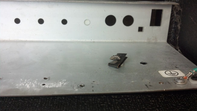
Just a little higher on the hardware evolutionary scale is this sheet metal nut, jammed over another wood screw. This was all coming out if my fingerprints were to be found on this thing!

The original line cord would be re-used with the new switch. Here, I have contrived a strain relief scheme involving a black wire tie and a wire clamp, securely bolted to the chassis.
Anyone who would pull on this would be able to pick up the amp and swing it around, although with a little practice amp like this, swinging it around would not be hard (but could be hard on the furniture.)

This is a closeup of the new power switch. The body of the switch was round, so the edges of the rectangular power switch hole in the front panel were enlarged slightly with a file so that the new switch fit properly. As you will see in a moment, the front bezel of the switch was rectangular, which covered the original hole nicely.
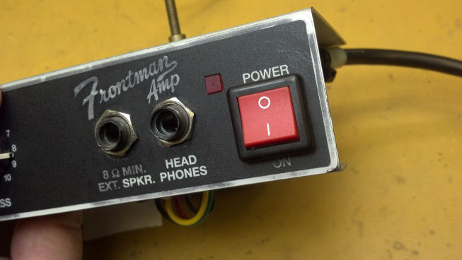
Not a bad job on the power switch, I’d say!

Some machine screws were secured that were the proper length and thread size. Here I’m bolting the chassis securely into the top of the enclosure.

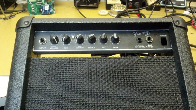
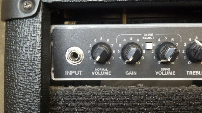
Everything is back together. On the right end of the panel, you can see the new Switchcraft steel input jack. It is wired directly to the chassis with short pieces of hookup wire. This jack will probably outlast the rest of the amp.
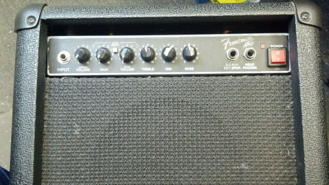
This is a front view, showing the difference between the steel input jack (on the left) and the factory Fender plastic jacks on the right, next to the power switch. By the way, the external speaker jack was also broken, but the owner did not need to use that feature so we left it as-is.

We are ON. The red LED was smashed back inside the amp, so part of the reassembly process was to secure it back in its hole in the front panel.
The customer was very pleased with the input jack. The amp works 100%, much to his parents’ chagrin. Rock n’ Roll!