Line6 M9 Multi-Effects Pedal Checkout

Steve really liked this pedal and gigged with it constantly.  However, one day, he found that he couldn’t control it through the stomp buttons.  The screen lit up, but nothing could be configured in the screen, and the pedal was useless.  The Unbrokenstring Crew rides to the rescue!

02 DisassemblyYogi Berra said “You can observe a lot just by watching.”  Sometimes, a little exploratory surgery will make the problem more apparent than going through the electronic menus.  We’re going in!

03 Disassembly
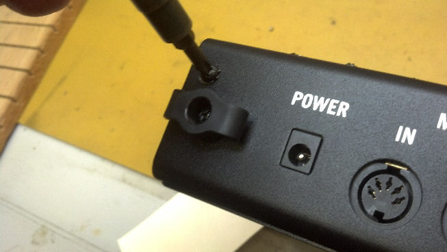
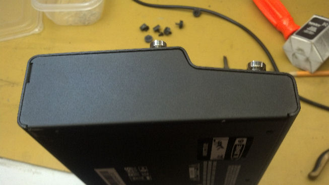
It’s a little tricky to get the halves apart, but a little patience and good lighting lets you disassemble the unit.

04a Red PCBsIf you design your own circuit boards, as I do, you can order your circuit boards with any color solder masks.  I see that Line6 used red.  I’m good with that.  Although I use red solder masks with prototypes, and green for production.

04b Red PCBsThe top row of stomp box buttons are fastened to the large circuit board at the top, with the DSP engine right in the middle.  The lower circuit board handles the bottom four stomp box buttons.  What do we have here?

04c Beer
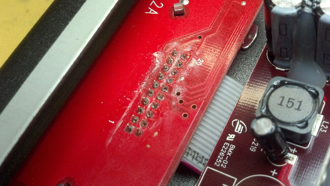
Nothing like a little spilled beer to brand this pedal as a gigging, mud/blood/beer-stained Texas Rock and Roll weapon.  But the beer is not the problem.

05 Cap1
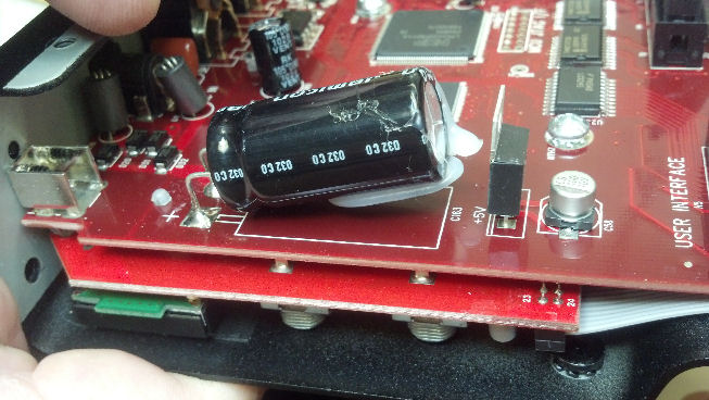
Nor is this the problem.  But it points us in the right direction.  Hot glue is commonly used in electronics, for encapsulation and adhesion.  Here, a blob of hot glue kept this cap down on the circuit board.  Or it should.

09 Hot Glue Magic
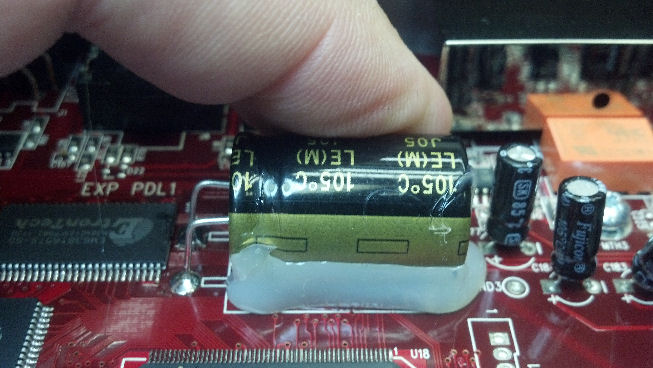
Here’s another big capacitor held down with hot glue.  Any guesses yet why this pedal failed?

08 Hot Glue MagicI’m using the hot air rework soldering iron to soften the hot glue and stick down the big caps.

06 Loose07 Thats Better


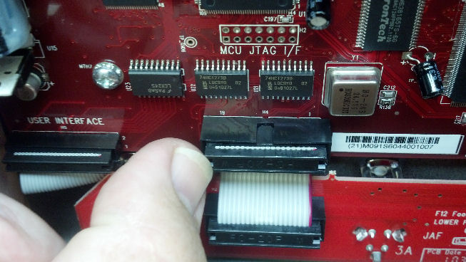
Do you see what I just did?  The pedal was dropped, and the force of impact unseated this connector.  And it dislodged the big capacitors.  Now that the connector is reseated, everything works fine.  Easy Peasy!

10 ReassemblyThe unit is reassembled and checks out fine!  The firmware in this unit is update-able through the MIDI port, so if you need to update an older unit, you will need to connect this unit into the MIDI chain on your PC or laptop as there is no USB configuration capability.  But the factory reset can be done through the menu, and is well-documented on the Line6 Web site.

Thanks for reading all the way to the bottom!

Contact Info :

David Latchaw EE

281-636-8626


Bogner Alchemist Amp Lives Again After Electrical Surge

A local musician lost this amp head during a gig.  The bassist also blew some fuses in his rig.  Everything failed at once.  Besides making a great testimony for carrying your own power conditioning equipment, a lot of stuff had to be fixed.  The Unbrokenstring Crew goes to work!

There were no signs of life other than the tube amp section appeared to be fine, and, surprisingly, the LEDs in the foot switch assembly lit up.  Some Google-ing revealed that Line6 built this amp, which included Line6 modeling technology to implement the reverb and other internal effects married to a Reinhold Bogner power amplifier.  Now that I could locate a manual, we could narrow down where the failure occurred.

There is a fuse holder built into the AC power receptacle.  All is OK here.

The Line6 design project was called “AV/Cali” and the “HD” on the sticker indicates that this is a ‘head’ version.

Moving out of the left side of the picture is another fuse.  OK here.  Let’s keep going.

I don’t know why the ETL sticker appears a little faded.  But here’s where the foot switch plugs in.

This effects loop specifies parallel connection.  Glad I’m not doing a pedal board for this amp!

With the grilles off, we see a little ‘bling’ including a custom-milled tube cover.  Wowsers!

The aluminum foil is a shield for the open bottom of the chassis.  This unit is well built.

This is a high-resolution pic of the bottom chassis wiring.  Click on the picture to fill your screen with tech porn!

There are a couple more fuses under the chassis that we need to check.  Here’s one…  No problems here.

Another fuse is reserved for the big transformer.  No problems here either.  It’s time to check the various supply voltages against the service manual.

What’s this?  This wire was pinched between the chassis and the amplifier enclosure.  The insulation is a little deformed but otherwise OK.  This was poked back where it belonged as this was NOT the problem.

We didn’t have the 3.5v and -3.5v power.  The schematic showed that this was derived from a single winding of the power transformer, sent through a full wave bridge rectifier, and filtered with a big capacitor.  The issue is somewhere around the rectifier.  Here, I’ve flipped the Power Supply Unit (PSU) board upside down so I can remove the rectifier to more easily troubleshoot the circuit.

These solder joints were cooked.  All the solder was removed and the holes cleared of solder.  Now I can see that the circuit board was open-circuit on the trace at the bridge rectifier.  The holes in the pads shown in this picture is where the bridge rectifier was.  I’ll fix the open circuit board trace with a short piece of wire when I put this part of the circuit back together.

Here’s the view of the board without the rectifier.  It’s a little hard to see here, but the bottom oval pad was cracked.  That will be repaired.  The rectifier is OK, so it all goes back together.  That is what you call ‘troubleshooting beyond the component level.’

All lights are on, all knobs work.  This beast is ready to go now!  I delivered this to the owner’s house as he lives on my way home after work, and he said “It sounds great!”

Thanks for reading all the way to the bottom!

David Latchaw  EE

281-636-8626

Custom Built Paul Reed Smith McCarty Standard

A friend of a friend had this beautiful Paul Reed Smith McCarty guitar refinished with an even more beautiful black finish. But, he encountered some difficulties putting it back together, and wanted me to look at his baby.

Everything had been buffed to better-than-new condition.  Some polishing compound remained as you can see here.

But some paint had dripped into the threaded bushings, and the owner was concerned that he would only damage the new finish more while trying to build this guitar.  So he called in The Unbrokenstring Crew!

04Bparts04Aparts


04Cparts04Dparts


We had a big bag of parts and a guitar body in a case.  Let’s get to work!

05CleanThreadsThe chip was touched up, then allowed to cure for a week.  Now, we’re protecting the finish of the guitar so that we can chase the threads in the insert.  I had considered just changing the inserts but didn’t want to take the risk at this point.

06TestThreadsAfter the threads were chased, a little bit of solvent was used to clear the bottom few threads.  Lots of protective, non-stick tape comes in handy when protecting a priceless guitar body!

07AjackThis is a nice shot of the new pre-wired jack, already attached to the jack plate.  The cabling was pulled all the way into the internal routed cavities of the guitar, where it would be attached to the selector switch.

07BjackOops, there I did it again.  A little Guitar Tech Porn!  This is a nice setup, regardless of whether you are a tech or not.

07CjackAll squared away.  On to the pickups.

08PolishPickupsOriginally, I thought that the hardware for this guitar was nickel.  However, these were used pickups, and had years of funk on them.  I made the executive decision that these should be shiny, because the rest of the guitar was shiny.

09PickupAssyYeah, that’s what I’m talking about!  By the way, treble pickups go closest to the bridge, and bass pickups go near the neck.  Which begs the question, what are the middle pickups in a three-pickup-guitar called?  Grand Staff?

10TempHoldThe pickups were temporarily held in place with this no-mar tape while the guitar was turned over to do soldering on the routed compartment on the back side.

11Wiring1The wiring diagram says that the taps go to the push-pull pot.  I added some heat shrinkable tubing to all the solder joints I made.  Too bad the factory doesn’t do this, because accidental shorts would be one less thing to worry about.

11Wiring2Here, the switch is wired up with the output leads from each pickup per the wiring diagram.

12FinalAssyWith everything wired up and working, the pickups could be fastened down.  See my earlier Jazzmaster posts about the method I use to check guitar wiring without any strings attached to the guitar.

13AssembleTuners1And now, off to the headstock.  These bushings were too tight to fit into the holes because of the additional layer of paint.  Each hole was hand-reamed until the bushings could be pressed into place.

13AssembleTuners2These tulip tuners give a Kluson vintage look to the guitar.  I just love the mahogany wood!

13AssembleTuners3More Guitar Tech porn.  We’re done with the headstock.

14BridgeThis TonePros bridge is an intelligent upgrade for wrap-around bridges.  Here, I’ve run the individual saddles to the far end of each string, so that the vibrating part of the string will always be straight and not deformed because it once was bent over a saddle.  We’re ready for strings!

15DoneThis guitar has a beautiful voice, and the owner was pleased with the results!  Oops, more Guitar Tech Porn!


Thanks for reading all the way to the bottom of this post!

David Latchaw

281-636-8626