Ashdown EVO II 300 Bass Head Repair

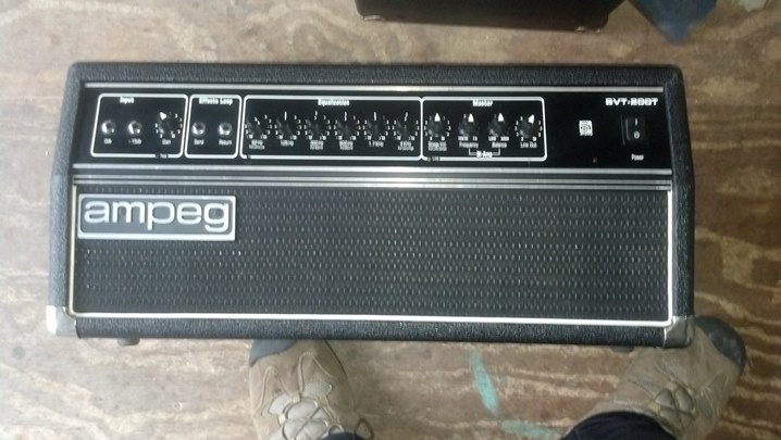
This British-made bass head was dead to the world.  After looking at the fuses, nobody would dare open it for service, possibly because there was no service literature available in this hemisphere, or perhaps out of reverence for the brand.  This is a hybrid amplifier, with a tube in the preamp chain and a solid state power amplifier.  Would the Unbrokenstring Crew run where angels fear to tread?

01ASH the patient
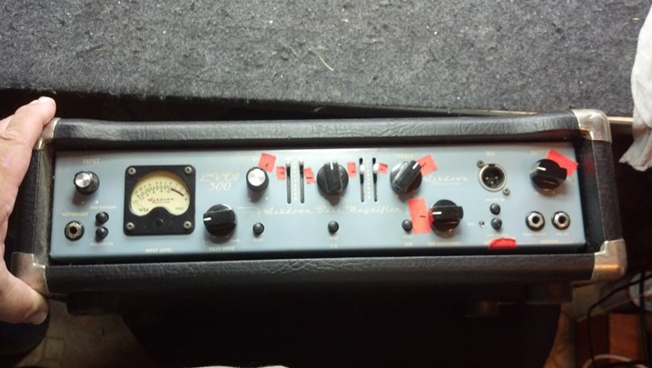
The owner said that he would clean up the front panel.  Just get the thing working.

02ASH backside
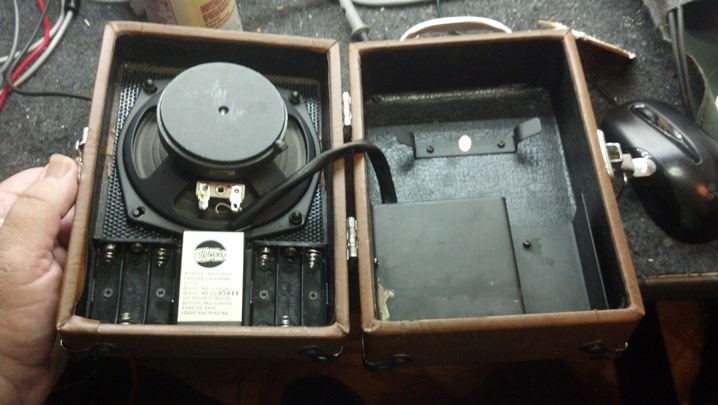
The steel chassis was just the ticket to keep everything in its place.  You can see the Trace Elliot heritage in this brand.

03ASH back close
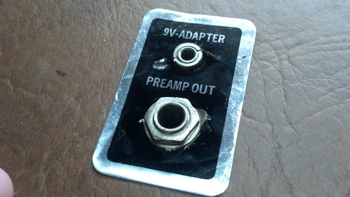
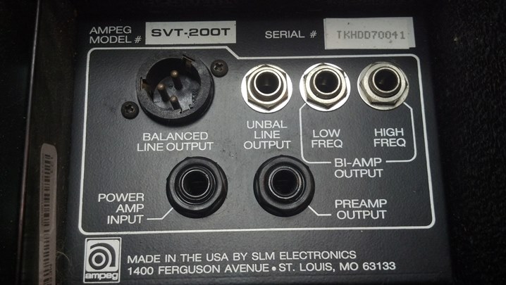
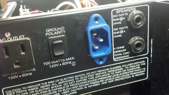
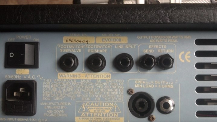
Here’s a close-up of the rear panel.  The footswitch must have a pair of switches and a pair of quarter-inch plugs.  The line input jack is an interesting feature.

04ASH chassis scr
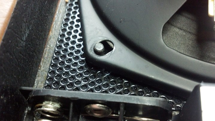
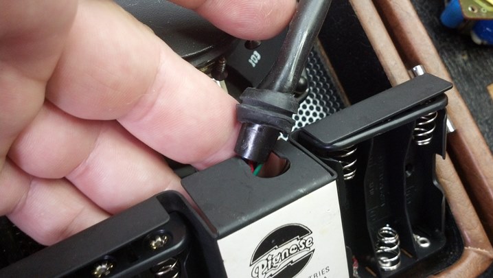
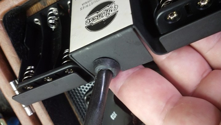
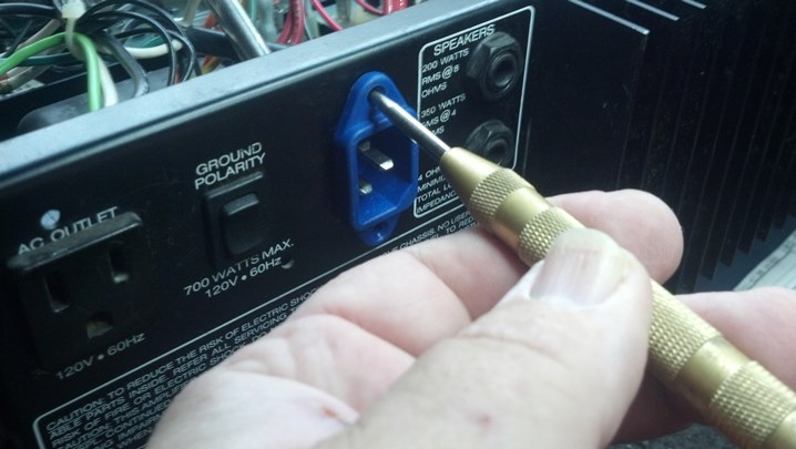
These plastic caps covered the screws that secured the chassis to the case.  Well, it appears someone has been here before us!

05ASH scr
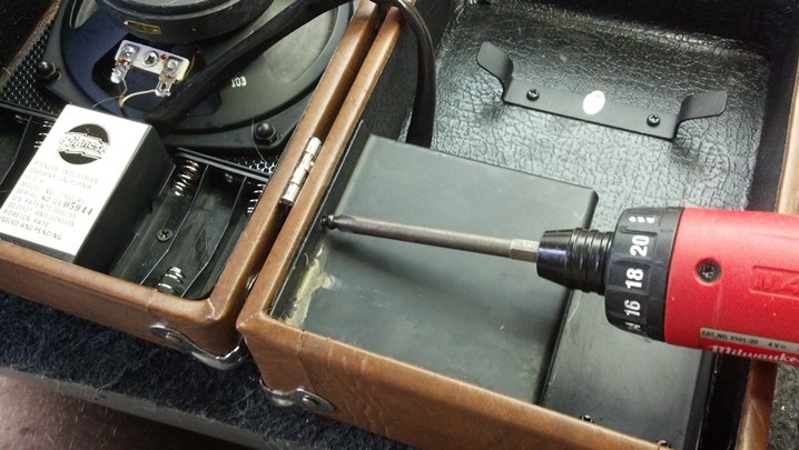
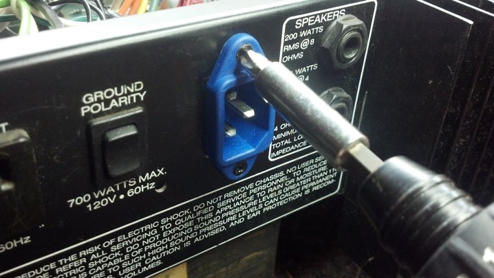
A little care and a #3 Phillips was enough to bite into these screws and get the unit open.

06ASH power supply
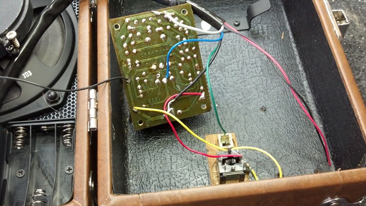
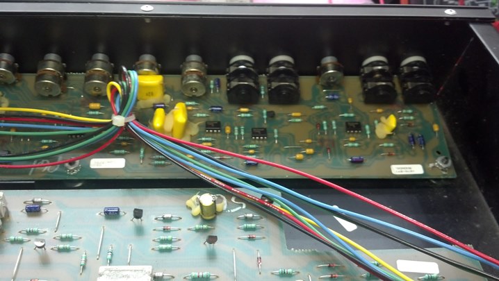
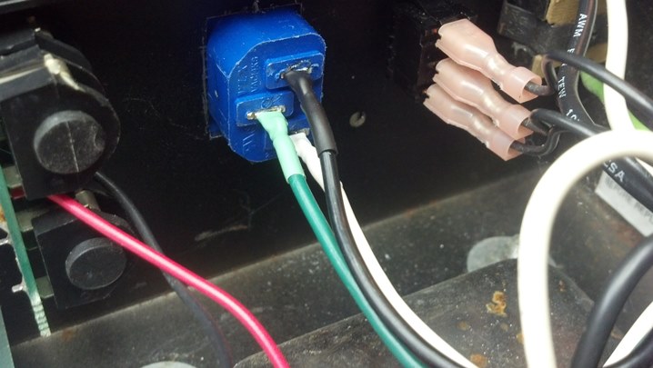
Here, the power amp board is pulled free for inspection.  That’s some big wire!

07ASH cooked
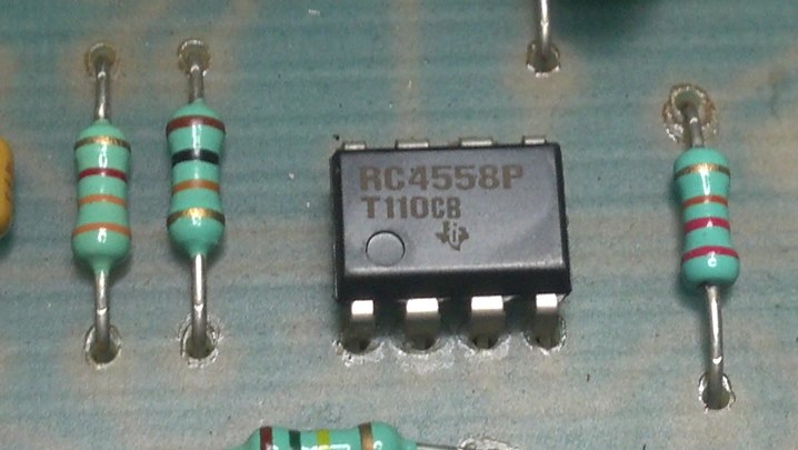
Can you see the failed solder joint?  The four elongated tabs are the terminals on a large full-wave bridge rectifier.

08ASH repair
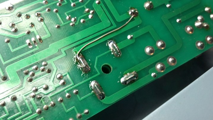
Each of the solder joints were de-soldered and then re-soldered with fresh solder.  The joint that failed may have been on an ever-so-slightly thinner trace, so a jumper wire adds some circular mils of copper to that part of the circuit to keep the temperature rise of the circuit board down.

09ASH on the air
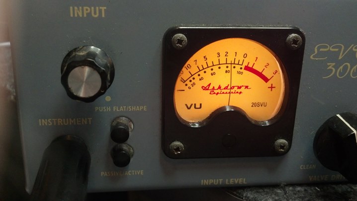
Behold!  Everything comes alive!  This meter is really a nice-looking feature.

10ASH finished
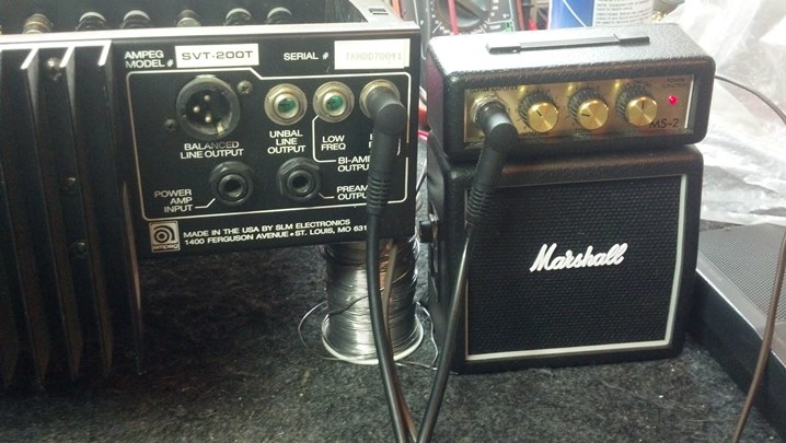
This unit is conservatively rated at 300 watts.  The unit barely got warm after four hours at that power level.  I think we fixed it!

Thanks for reading all the way to the end!

CONTACT – David Latchaw EE
281-636-8626

Pignose 7-100 Mini-Amp Refurb

This battery-powered portable amplifier is a novelty item seen in offices, bedrooms, and showrooms around the country.  This little guy doesn’t work anymore.  Could the Unbrokenstring Crew make it work again?

01PIG the patientThe pig’s nose is the on-off/volume control.  The input jack is just below the nose.

02PIG insideInside, we find a loudspeaker and battery box on the left, and the electronics and some cord storage on the right.

03PIG missing nutThis nut is missing.  Oh boy, this is Big Trouble in Little China.

04PIG acid everywhereThe cover over the electronics shows signs of corrosion, probably from battery acid.

05PIG found nutGood news!  We found the missing nut.

06PIG jacksThis panel is on one side.  Surprisingly, the power jack is ‘old technology’ and probably should be the same connector as seen on effect pedals.  But, hey, they didn’t ask me.

07PIG nameRankSerialThis metal piece secures the battery boxes in place.  Name, rank, and serial number please.

08PIG new bat boxThe original battery box was trash, so these units were procured.  Six batteries give us nine volts.  These x3 packs are necessary to fit into the space provided.

09PIG acid here tooCaustic chemicals from the leaking batteries were conducted, via capillary action, over to the amplifier side of the box.  A new pair of red and black wires were fished through the umbilical, replacing the corroded wires.

10PIG wired boxesHere, the new battery boxes are wired into the unit’s harness.

11PIG fitting boxesThe battery boxes rest on a metal bracket, which also serves as a noise shield over the volume control and input jack.

12PIG Strain reliefThis grommet serves as a strain relief for this end of the umbilical cable.

13PIG looking goodThis pic just shows how the leads are dressed. This unit is small, and the wires need to go into their correct places in order to close the unit up when we’re through.

14PIG watch lead dressThese red and black wires can be pinched between the case and the metal plate, so they need to be pulled up and out of the way before the screws are tightened down.

16PIG clean ampWe find the preamp and amp in the other side of the unit. The small assembly seen at the bottom is back side of the power jack and the ‘preamp out’ jack.

17PIG reinstall ampThis assembly was covered with caustic chemicals from the leaked batteries.  Miraculously, these transformers were not damaged.  Everything cleaned up very well.

18PIG cover onThis cover shields the amp and jacks.  We’re done here.

19PIG batteriesA fresh set of batteries and a twist of the knob puts this unit back on the air.  Time to call the customer!

Thanks for reading all the way to the end!

CONTACT – David Latchaw EE
281-636-8626

Ampeg SVT-200T Bass Head Update to IEC AC Power Entry

This absolutely mint-condition solid state bass amp head came through the shop for a quick once-over.  More significantly, the owner wanted one of those new-fangled IEC AC power jacks installed in place of the existing power cord.

01SVT the patientThese units are highly regarded by many bass players.  Some consider them to be an equal to the tube-based models in the realm of versatility and sound.  And they are sure a lot lighter to carry around!

02SVT line outsThe rear panel is straight forward, with everything you need for a decent bass amp setup.  More goodness from St. Louis Music Electronics!

03SVT amp1Inside, we have the interface to the front panel and some power transistors.  The unit with two flag terminals is a thermal switch that opens when the heat sink gets too hot.

04SVT amp2Here we have more power transistors and the driver transistor pairs.

05SVT amp3Power supply capacitors and the choke are found on this end of the board.

06SVT amp4The power transformer is bolted here, and the input protection circuit board is mounted on the side of the chassis.

07SVT fp1Input jacks and controls are found in this view, facing the back of the front panel.

08SVT fp2This is the rest of the front panel.  Note the big solid state rectifier for the power supply in the center foreground.

09SVT technologyAmerican-made Texas Instruments semiconductors are widely used throughout this unit.  Here is a preamp chip.

10SVT cordThe original line cord is removed with a snip.  The wire remaining inside the chassis will be soldered directly to the IEC connector.  The big chunk of insulation will be removed.  The AC wiring will then be dressed in the same manner as the rest of the under-chassis wiring.

11SVT pwr inThis blue IEC connector will be installed in the rear panel where the strain relief bushing goes.

12SVT hole dimsA rectangular hole will be cut to mount the IEC connector.  The pencil lines show up pretty well in this view.

13SVT magnetA magnet is positioned to keep the metal chaff from the sheet metal nibbler away from the electronics.

14SVT holeThis is the rough-cut hole.  More filing will gun-smith this into a rectangular shape.  Note the handle on the magnet visible through the rectangular hole.

15SVT trial fitHere, we are trial-fitting the IEC connector.

16SVT screwholeThe location of the hold-down screws is marked with a center punch.

17SVT drillNow the holes for the screws are drilled, as you might have guessed.

18SVT trilobed scrThe machine screws are torqued, mounting the IEC connector in its new home.

19SVT magnetsThe magnets have really done their job.  None of these filings will be left loose inside the chassis!

20SVT wire prepThe cut ends of the power cord inside the chassis are stripped and tinned.

21SVT shrinkAs a nice touch, some heat shrink tubing of the correct color is slipped onto each wire.  Pure cosmetics!

22SVT solderThese are tacked into place for now.  Before the final joint is made, I’ll verify that the wires go to the right place!

23SVT shrinkWiring orientation is confirmed as correct!  The soldering was completed and the heat shrink tubing is shrunk into place.

24SVT line out testHere, I’m checking the functionality of the low-level signals to feed a bi-amp setup.  Note the Marshall Stack!

25SVT final testThis unit is ready for the 21st century.  The modular cord makes setup and transportation more convenient.


Thanks for reading all the way to the end!

CONTACT – David Latchaw EE
281-636-8626