This combo amp had lived a hard life and had finally quit. Grandpa wanted his grandson to get the amp fixed so that they could jam together again. Could The Unbrokenstring Crew bring this unit back to life?
 We begin with a quick tour of the rear panel. The ground switch is a tip of the hat to the Old Days of two wire AC.
 The foot switch plugs in where the REMOTE SWITCH jack is coming loose. This gets fixed.
 I’m surprised that this hadn’t ripped loose. The whole connector wil be replaced.
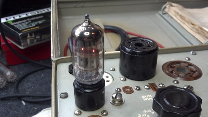
![]() Name, Rank, and Serial Number, please!
Name, Rank, and Serial Number, please!
 What have we here? We found grandpa’s stash.
 Let’s get this line cord wired correctly. Do you know what’s wrong?
 The black wire goes under the brass screw. “Black on brass will save you ass.” You’re welcome.
 The reverb tank connects to the main circuit board with this connector.
 Even after all this time, the high voltage capacitors are still charged. Woah! This is my discharge wand at work.
 Our first mystery… where does this nut go?
 This is a fuse. No, you think that it is a piece of 16AWG wire, but it is a fuse. Or, it is where a fuse goes.
 And here, someone was tired of the fuses falling out of the holders, or what was left of the holders.
 The heat from the flow of current has wreaked havoc on this solder joint.
 This probably smelled bad when it was hot.
 Now that the introductions are out of the way, we need to start replacing this nonsense.
 These are commercial fuse holders. These will replace all of the preceding nonsense.
 The plan will be to install these new fuse holders at a spot in the circuit where they will be functional, yet out of the way.
 The new fuse holders are held down with a screw. This hole is where the screw goes. Here goes!
 Another hole is drilled for another fuse holder.
 This hole is in the center of a trace. We won’t miss that copper. Much.
 Insulating nylon nuts and bolts are used to keep the new fuse holders in place.

The traces in the burned circuit boards are replaced with this Teflon-covered wire.
 Everything is now stuffed back into place. Not too shabby, if I do say myself.

Turning our attention to the rear panel, your sharp eyes may recognize this connector as a MIDI female panel connector.
 To keep the connector hardware in one place, some of this Thread Locker is all we need.
 We have the original foot switch. It needs a new cable, with a connector to match what we just installed in the amp.
 This MIDI cable will be repurposed to replace the cable on the footswitch assembly.
 We don’t need this connector. Instead, this end of the cable will be wired to the switches themselves.
 The new cable is soldered directly to the switches Note the strain relief installed to the right of the picture..
 This pedal is ready for action once again!
 The amp is reassembled and is ready to go!
 The four hour burn-in test is underway. I think we have rescued another vintage Peavey amp!
Thanks for reading all the way to the end!
CONTACT – David Latchaw EE
281-636-8626