
A fellow musician gave Charles this amp, which was nice gesture. However, the friend said that it was intermittent. Could the Unbrokenstring Crew turn this gesture into a reliable amp?
 Styled as a unit from the Fender Brownface era, the exterior certainly checks all the boxes for Brownface goodness, with the Correct knobs and silk-screened front panel true to the archetype. One channel is reserved for an instrument, and the other channel is tailored to vocal performance, including a dual XLR/quarter inch jack for a microphone.
![]() No metal shredders allowed. This unit has a tweeter, and an electronic gain structure that does not distort. Just the thing for Charles’ acoustic act. This badge still has the protective plastic in place.
No metal shredders allowed. This unit has a tweeter, and an electronic gain structure that does not distort. Just the thing for Charles’ acoustic act. This badge still has the protective plastic in place.
 The speaker cabinet is sealed. This polarized connector keeps three pairs of audio signals from the amp going to the correct loudspeaker and tweeter.
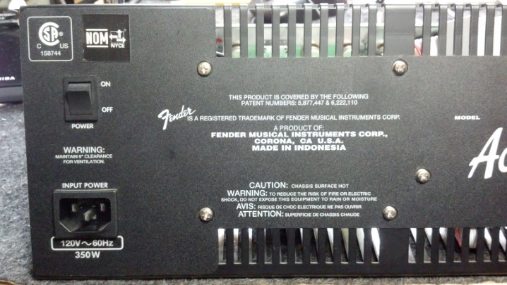 On the back side, we find the ON/OFF switch and the IEC power socket. Most of the rear panel is slotted for ventilation.
 This is a solid state unit, with plenty of pep to be loud.
 The internal architecture permits stereo operation, as is shown by the FX loop connections. I did not play around with the USB functionality, but it’s in the manual. We have bigger fish to fry.
 Name, rank, and serial number, please.
 This circuit board holds all the connectors for Line Out and effects loop functionality, as seen on the rear panel.
 This assembly is an AC to DC power supply on the left, and an efficient Class D audio amplifier on the right.
 Digital signal processing (DSP) is used to create the reverb and other effects. The DSP functions are on the mezzanine board on the left. The thin white cable in the center is the USB cable. The main printed circuit board handles the clean audio chain and the connections to the front panel controls. The flat cable on the right brings power from the AC to DC board and sends audio to the amplifier.
 A lot of surface-mount components are found in this unit. Those little cans are electrolytic capacitors; black squares are integrated circuits. Each of those little black squares does the job of two vacuum tubes. I feel old and obsolete.
 The check mark probably means that someone tested this at the factory, I guess.
 So the audio processing hardware is seen at the top of the picture and the power stuff is at the bottom.
 The AC wiring comes from the switch directly to the circuit board, where there are filters and a fuse.
 This power stuff is actually a switching power supply, which efficiently creates the various operating voltages.
 If you look closely at the gold rings on the circuit board, you will see solder that looks ‘strange.’ It does. Gold atoms mix into the molten tin/lead alloy while the solder joint is in the liquid state. The gold makes the solder brittle.
 The entire circuit board is gold plated. This plating is among the flattest finishes available for bare circuit boards, perfect for surface mount technology (SMT) components but is a metallurgical compromise for thru-hole components..
 As you can see, for thru-hole technology components such as these pins sticking through the board, the results of the soldering action can leave something to be desired. Do you see the holes in the solder joints?
 Now that those holes are fixed, we can focus on the real source of the intermittent operation. Do you see that light blue resistor with two red stripes hiding behind the capacitor and the heat sink?
 That light blue resistor was soldered here. Or to be more precise, it was soldered there at one time. The cracked solder joints became intermittent conductors. Here I have removed the resistor and cleaned away the old solder in preparation for making a new pair of solder joints, free of gold contamination.
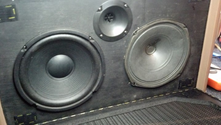 Another issue with this amp is that someone has been playing with the loudspeakers.
 This loudspeaker fits the cabinet perfectly, but electrically, it is a 40 ohm (yes, forty ohm) loudspeaker, designed for use in a public address paging system (you know, that mess that you hear at the doctor’s office playing MUZAK, mercifully interrupted by an announcement for someone to call a telephone extension? Yeah, that.)
 The Correct part is available.
 Who would have thought that you could actually replace a bad loudspeaker with a new one of the correct type?
 Do you like those TV shows where they have a build-up to the ‘Big Reveal’? I don’t either.
 Fortunately, we have the correct part and are ready to install it.
 Once we replace the grille, you will never know the difference.
 See, I told you that you couldn’t tell the difference. This unit plays beautiful music and the functionality is solid.
Support this musician, winner of a Texas Music Magazine 2018 Album of the Year: http://www.charlesbryantmusic.com/
Thanks for reading all the way to the end!
CONTACT – David Latchaw EE
281-636-8626


