The original neck on this MIM Black Strat was made from wood that tended to twist when the string tension varied, either because of temperature changes or when employing different string gauges. It’s now time to take this guitar to the next level, and make it an iconic Blackout Strat
.
The neck will be retired to another instrument.
.
This instrument was built in 2006, which happened to be the 60th anniversary of the founding of Fender Corporation.
.
The neck is off and headed to its new home.
.
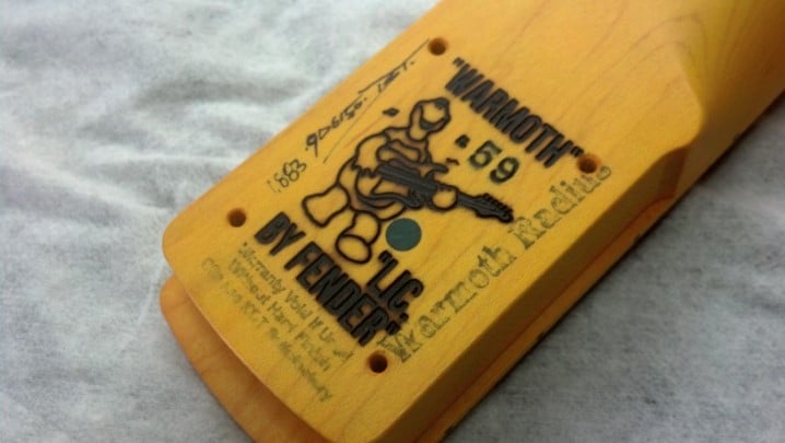
David Gilmour’s Blackout Strat has a maple fret board. This instrument will get a new maple neck, with a 59 ‘C’ contour and an almost 2 inch wide nut. With light strings, this guitar will feel like a nylon-stringed classical guitar.
.
The aftermarket Fender tuners are lined up with the machinist’s rule and tightened into place one by one.
.
These tuners are ‘locking’ tuners, which positively grip the end of each string in a clamp. This is necessary on this instrument because of the very light gauge strings we will be using.
.
Head stock and nut are ready to go.
.
The middle pickup appears to be not working. Let’s take a look inside.
.
Sure enough, there is a broken wire inside the pickup cover.
.
The break in the wire is literally in the very last turn! So one turn is un-spooled and threaded through the eyelet where it belongs.
.
As was done at the factory, the wire end is pulled through the eyelet a few times and soldered in place.
.
The middle pickup is tested and is right where it should be.
.
The Classic(al) Blackout Strat is strung with 7 gauge strings; Yes, not 12s, not 10s, but with Billy Gibbon’s own Dunlop Reverend Willy Extra Light Electric Guitar Strings, .007-.038. With the proper setup, this instrument has the play-ability and feel of a nylon-strung classical guitar. Thus, we have the Classic(al) Blackout Strat.
A famous Houston Jazz Cat sought out the services of The Unbrokenstring Crew after hearing about us by word of mouth. This instrument was at home on the stage and in the studio, but just needed a little something more. Could The Unbrokenstring Crew supply that ‘little something more’ and get it done before this Friday’s gig?
.
This instrument was a dead-stock, straight-ahead jazz bass, just a little funk added in for fun.
.
We will reuse the strings, so they are just pushed back through the bridge to get them out of the way. The original bridge pickup is already loose from the body.
.
A peek under the cover shows the smooth, unscrambled, automated winding used on these factory pickups.
.
To access the neck pickup and get to the wiring more easily, the pick guard is removed.
.
Black and white wires go to the neck pickup. So far, so good.
.
And, black and white wires go to the bridge pickup. We need to keep all these wires straight. Or gently curved, as the case may be.
.
The burned insulation and cold solder joint on the tone pot tells me that the factory wiring was done in a hurry. The Unbrokenstring Crew is in a hurry, but not this much of a hurry.
.
The original neck pickup ohms out at 5.14k ohms.
.
The original bridge pickup is not that different, measuring 5.51k ohms. The original pickups were labelled and returned to the owner.
.
Our Jazz Cat chose these pickups for his instrument.
.
Rio Grande pickups are built here in Houston, Texas. FYI, for the last five years, customers of The Unbrokenstring have asked to have Rio Grande pickups installed in their instruments more than any other brand.
.
The Unbrokenstring Crew is curious about how these new pickups measure up. On the screen of the Fluke meter is the resistance reading of the new neck pickup. A lot of wire is used to make this pickup!
.
This is the resistance of the new bridge pickup.
.
Wiring for the bridge pickup is snaked through the bore in the body, along with the cavity ground wire. The pick guard does not cover this part of the instrument, so cavity wiring needs to be tunneled through the body.
.
The bridge pickup settles into its new home.
.
Wiring the neck pickup is a little easier as the control route extends to the neck pickup cavity route. With the wiring done and everything temporarily in place, a quick sonic check is performed with my Massive Marshall Full Stack.
.
The J-Bass is reassembled and ready for re-stringing.
.
If you look closely, the brand name on the pickup covers can be seen. Pickup height is approximately same value as was used to install the original pickups, but our Jazz Cat already has his #1 Phillips screw driver ready and will set the ‘just right’ height by ear.
In Part Three of this project, The Unbrokenstring Crew installed a unique cut-out switch in the pick guard of this guitar. One more thing… Now that the instrument is play-able, the original plastic Squire nut is cracked. Grrrr…
.
The old Squire nut came out in pieces.
.
Let’s make a new one from Vietnamese water buffalo bone. The blank we’ll use today is shown above the old Squire plastic nut.
.
Not to brag or anything, but these bone nuts are truly a renewable resource that I am privileged to legally import from overseas. CITES can go bite it.
.
The eighth inch chisel easily cleans whatever glue Squire used to install the original plastic nut.
.
This slot is ready for the new nut.
.
Sorry, that’s as clean as I can get it.
.
The new blank nut is thickness-sanded to fit the slot. I’m doing this by hand because the blank is very close to the proper dimensions to begin with.
.
The inside radius is established by using the actual neck as a radius block.
.
The side contour is also established by hand, on the actual instrument.
.
The actual height of the fret wires is measured in order to calculate the depth of the string slots. This dial indicator measures the installed height of the fret wire above the finger board.
.
Here, we’re gluing the new nut right to the finger board using hide glue. A water-based adhesive could cause the wood to swell; shrinkage over the next few months as the wood dries out would throw off the accuracy of the nut slot depth. Can’t have that!
.
The old nut is used as a template to establish string spacing. A couple of old strings are used to align everything.
.
Now that we know the fret height, string gauge, and string spacing, we can begin establishing the string slots. At the nut, the string slot depth is constant across the radius of the finger board, regardless of the string diameter.
.
With a set of old strings in place, the top of the nut can be quickly contoured so that the top of the nut will not protrude above the strings. The geometry of the top of the nut is established in part by the diameter of the strings, which is, of course, not constant across the radius of the finger board. This three-cornered triangular file belonged to my father.
.
This old triangular file is just the thing to contour the nut further, smoothing out sharp corners and preparing the nut for polishing.
.
Note that the string centers are just below the top of the nut, and that the top of the nut is no higher than any string.
.
This is the instrument, as delivered. The Vietnamese water buffalo bone is a spectacular material for musical instruments: incredibly hard, uniform throughout its bulk, and capable of a fine polish without additional waxes or oils, making a visually attractive nut and providing a stable, polished string slot that allows for smooth and stable tuning without binding or sticking. What more could you ask?
I think we’re finally done with the Jagmaster Make-Over!
In part two of this series, The Unbrokenstring Crew converted this instrument to a Tune-O-Matic bridge with a Bigsby tremolo. Now The Unbrokenstring Crew will add a cut-out switch to this instrument.
.
Matt has specified this exact spot where he wants the cut-out switch installed. The sharp point of an Exacto knife marks the exact center of the hole where the new switch will reside. Because that’s why they call it an Exacto knife.
.
We need to remove the pick guard, so off come the strings. Again.
.
This nylon washer is used in the Bigsby system to, among other things, set the working height of the lever. Keep track of this!
.
A pilot hole is bored where the Exacto knife made the mark seen earlier.
.
The copper foil around the new switch hole is cleaned. We are now ready to install the new switch.
.
The resistor is installed across the contacts to limit the audible ‘pop’ that you sometimes hear when switching low-level circuits, like the circuits found in guitars.
.
Step Three is complete. This switch is not a push button, but is a spring-loaded momentary, center-off switch. Matt can quickly flick it from side to side for a very cool effect.
But wait! There’s more! In the last installment of this project, the cheap Chinese plastic nut has cracked. Tune in to see how The Unbrokenstring Crew upgrades the nut. Like A Boss.
In our first installment of this project, The Unbrokenstring Crew installed some new pickups in this cool offset-waist Jagmaster. Now, The Unbrokenstring Crew takes a deep breath. The inserts for the Tune-O-Matic will fall right at the edge of the body route for the Fender tremolo block. Extensive modification of the body is necessary for the next steps.
.
So The Unbrokenstring Crew takes an inspiration break. The first Fender-style guitar we’d seen with a Tune-O-Matic bridge was Larry Carlton’s Valley Arts ‘Strat’ copy, seen at about 9:10 in this video from 2012. WARNING: lots of funny Guitar Face to be seen throughout the video.
.
To position the TOM (Tune-O-Matic) bridge, we need to verify the dimensions of the guitar.
.
The twelfth fret is just to the right of the fret board marker. If you double that measurement, you get the ‘scale length’ of the guitar.
.
This metal machinist scale is eighteen inches long, so to complete the measurement to the bridge, we moved the end of the scale to the twelfth fret.
.
You will see that the existing bridge saddle blocks fall around the same place on the machinist scale. This looks good so far.
.
It’s time to get serious. The patient is prepped for major surgery. The black wire seen in the picture is the spring claw ground and the ground wire for the pickups.
.
The claw is coming loose and the springs will be removed.
.
After the new bridge and tremolo are installed, we won’t be needing this claw anymore.
.
With the spring tension gone, the original bridge just falls out. These inserts, though, should be tight, and they are not.
.
Both of the inserts had broken out. This points to the main concern with this modification e.g. how to install new inserts for the TOM bridge, in the right place, with enough wood around them to assure mechanical stability and sustain. This was a significant question in the planning stages of this project.
.
With the pick guard assembly temporarily in place, we can begin to establish the geometry of the new parts.
.
The outline of the pick guard is lightly traced on the surface finish of the instrument. The starting (and ending) finish is matte black. This gives us considerable flexibility when doing the modifications and refinishing the instrument when modifications are finished.
.
Some tape holds the machinist scale in place, leaving our hands free to do some marking down on the body.
.
The TOM bridge will go about here. Guitar Cognoscenti advised that the TOM bridge should go about 8/64ths of an inch beyond the 1x Scale Length for the instrument, because of the increased string length which occurs when the string is deflected when fretted, and other effects. Thus, the mark for the center line of the TOM bridge is at the 12 and 56/64ths point under the machinist scale.
.
The measurement made in the previous picture is expanded across the battle space so that the TOM inserts can be properly placed. Do you see the issue with the new TOM bridge placement?
.
While we have the 24 inch artist’s scale out, let’s check to see what sort of clearance we have under the plane of the fret board to verify that the TOM bridge will fit. If it doesn’t fit, we can shim the neck up a bit and create more clearance.
.
The exposed end of the ruler gives us an idea of where we are on bridge and neck geometry. This number goes into the notebook for later. Oh, and we have both English and metric systems well-represented here.
.
Let’s move to the other axis, and establish the actual center line of the guitar. A string is fastened at the nut between the D and G slots.
.
The position of the neck is the determining factor of where the bridge shall be, not necessarily the guitar body; There will be room for adjustment later if we need it, but let’s get it right while we’re here.
.
The center of the bridge is marked on the tape.
.
Before we go any farther, the original bridge is placed back on the body as a sanity check for the work done so far. As if sanity had any meaning at this point…
.
Another number to go into the notebook is the original string width at the bridge. As we planned, the TOM bridge string spacing is really close to this measurement.
.
The breakout from the original bridge inserts need to be addressed, because we really want as much solid material in this area as we can get.
.
Both inserts broke the body out. Some instruments are best repaired by just router-ing out the entire top and substituting a slab of maple. However, with the routes on the back side, nothing would be left of this guitar body.
.
These chips will be glued back where they belong, using hide glue. We avoided using a water-based adhesive such as Tite-Bond because the wood would swell from the water, then gradually shrink again over the next few months, rendering our efforts to fill all the cavities moot.
.
This damage is repaired well enough to support the steps to follow.
.
Birch is the less-beautiful cousin of maple. It has very little figure, and is very straight-grained. These birch dowels are perfect for filling the original holes where the inserts were installed.
.
After adding some protective tape, the dowels are cut flush with this Japanese saw.
.
I like this saw. So you are going to see lots of pictures of it today.
.
I think you get the idea now. Yes, I like this saw!
.
The blue strip that you see is the edge of the blue masking tape seen above. Note how close the edge of the routes are to the center line of the new bridge. All this needs to be filled-in so that the new inserts can be secure.
.
We will work on this side for awhile. The neck is off and is out of the way.
.
Much of the paint in the interior of this body is conductive shielding paint. Paint is not a good surface to glue anything to, so the Dremel tool and a sanding drum removes it all. This body is actually some very nice wood!
.
Paint is removed all the way around the tremolo block route. No electronics will go down here, so I’m not worried about shielding.
.
The tiny lip remains at the bottom of this route. This lip is actually on the front face of the body of the guitar. The Unbrokenstring Crew will leave it in place as a depth guide when installing the filler blocks.
.
Since the neck was off, we took a moment to clean up the bottom of the neck pocket. A clean, hard neck pocket is essential for good guitar tone and sustain, as it forms the counter-spring for the strings themselves.
.
Only the bottom was scraped, and then only enough to remove any soft, crumbly finish. The sides remain unmolested as they establish the geometry of the guitar, which we documented earlier.
.
Two blocks will be fabricated to fill the trem block route. The paper patterns are on the left, and the block of spruce plywood is marked with the approximate shape to fit the route.
.
These blocks are fitted to the original trem block route.
.
The faces are cleaned up just enough to allow the glue to do its job when these are installed.
.
These will stack into the body route. Do you see the little strip of glitter to the left of the spring route? That’s the original color of this guitar. Can you say “Glam”?
.
We were able to source this NOS bridge from a company that purchases broken guitars from Big Box Retailers and separates the brand new parts from the firewood.
.
This is the first meeting between the new bridge and the guitar body.
.
This brad-point wood bit makes a good center-finder. This bit is exactly the same diameter as the inside diameter of the stud hole in the new bridge. Everything is arranged so that the point falls on the center line drawn on the blue tape.
.
A shallow marking hole is then drilled to mark the spot.
.
This picture clearly shows the issue with adding a TOM bridge to a Squire body. There is no substantial wood around the hole where the inserts will be installed. Yet, we press on!
.
One last trial fit is performed for these filler blocks.
.
These plugs are ready to go.
.
These are a good, tight fit into the original trem route. Can you see the glitter?
.
The top side should be flush. The lip inside the route was left behind to align the plugs already in the body. Another piece of birch will fill this shallow cavity.
.
This little bit of solid birch is fitted to the opening.
.
Hide glue is applied liberally and the stack of filler blocks are glued into place.
.
With the glue dry, we are ready to keep moving on this project.
.
The top is masked off again so that the top of this filler block can be completely level with the rest of the guitar.
.
A cabinet scraper brings the top of the filler block down to the level of the top of the guitar, or at least to the same level as the masking tape.
.
We cheated and used some wood filler to close up all the gaps. This will be finish sanded after one more coat of filler.
.
For additional internal strength and rigidity, another block is fabricated to fill a bit more of the spring body route. The same birch plywood is pressed into service.
.
The new filler block is a very tight fit. The paint around it will be sanded away so that the glue around the block can bond directly to the wood of the guitar body.
.
This new filler block is now glued into place. You can see a layer of hide glue on the filler blocks already in place in the trem block route.
.
The matte black finish was matched, leaving only the pilot holes for the new TOM inserts. All of the remaining body routes will be foiled and grounded at the output jack. We are covering some interesting shapes today!
.
The pickup cavities are done.
.
The control cavities are completed. The copper looks spectacular against the matte black of the body of the guitar. Here you can see how the matte black finish came out over the unfinished filler blocks installed previously.
.
While we’re at it, let’s do the underside of the pick guard. Note that the seams of the tape are tack soldered. The seams inside the body are also tack soldered, to form a continuous shield.
.
A small tab of foil extends from the body routes so that the foil under the pick guard can be bonded together using a pick guard screw for compression.
.
Next, the holes for the inserts will be bored using this brad-point bit.
.
The tape marks the correct depth. We don’t want to drill all the way through the guitar, do we?
.
I couldn’t help myself. I had to place the new bridge where it goes just to gratify my curiosity.
.
And while I’m gratifying myself, let’s check the position of the Bigsby.
.
As we begin slowly boring the holes for the inserts, we can clearly see the boundary where the body ends (on the left) and the filler blocks begin (on the right.) This is one spot where we need the most strength and rigidity for best tone (and to keep the guitar from falling apart under string pressure.)
.
This aircraft drill bit is boring a passage for the ground wire that will engage the bridge insert. To the left of the picture is another dowel rod.
.
That distant dowel is in a hole on which the Bigsby is mounted. Using the eighteen inch long aircraft drill, we need to slant drill our way through the guitar body and hit that hole. Somehow.
.
More blue tape indicates just how far I must drill through the body. If I don’t hit the dowel by the time the tape hits the copper, I missed.
.
Inhale. Exhale. I hit it! Some wire left over from the spring claw is pushed through the holes drilled in the previous pictures. Yes, that wire made a ninety degree turn inside the body of the guitar. Kind of a big deal.
.
Using the Exacto Knife, the insulation on the wire is nicked in the proper spot so that the insulation can be removed, allowing the wire to touch the bridge insert, thus grounding it.
.
The insulation is removed so that the wire can form a compression joint with one of the bridge inserts, thus grounding the bridge.
.
The big clamp can apply plenty of force to seat the bridge insert. The one on the far side has already been pressed into place.
.
The ground wire is now joined with the wire from the pick guard shield and soldered to the foil in the control route.
.
The free end of the ground wire is stripped and ready to be compressed against one of the Bigsby mounting screws.
.
When the Bigsby is installed, the screw that goes here will compress the ground wire and make the electrical connection, thus grounding the Bigsby tremolo and strings. No wiring will be visible from the outside of the guitar.
.
Here is the newly-installed bridge and trem. The pick guard is placed temporarily for this picture. This project is shaping up well!
.
The Correct pick guard screws are now in hand and will replace the larger screws originally used on this guitar. The holes are partially filled with birch dowels and cut flush.
.
The exact center of each pick guard screw hole is established with this pocket drill bit.
.
Once the center is established, the hole can be bored using the Correct bit.
.
This was a goof. The outside of one of the TOM bridge inserts interfered with this corner of the pick guard. The drum sander on the Dremel tool corrected the oversight.
.
Here, we are finishing up with the pocket drill. I use the electric screw driver as a drill because it is slow and easy to control.
.
This is a good shot that shows the modification of the pick guard to fit the TOM bridge insert.
.
To assure that the studs fit snugly in the inserts, some copper foil is used as a shim over the threads of each stud to make electrical contact and to help lock the stud in place after adjustments are made.
.
Copper foil is added or removed until the stud fits snugly regardless of how much of the stud is threaded into the insert.
.
Little bits of copper foil are all it takes to get these studs shimmed up where they belong!
.
It’s time to string it up!
.
It’s a lot easier to get the strings on a guitar with a Bigsby if the ends are pre-formed to wrap around the roller.
.
TOM bridges are versatile insofar as the saddles can be removed and turned around to extend their adjustability. Note: do not lose these little clips. Don’t ask me how I know this.
.
Once the clip is off, the adjustment screw can be unthreaded from the saddle.
.
The bevel on the top of the block can go either direction. We can use this to our advantage when setting intonation.
.
This saddle has been turned around.
.
The screw keeps the saddle in place.
.
And the little clip keeps the screw in place. Again, don’t lose these.
.
We took a detour to de-burr the hole in this tuning machine. This tuning machine was masquerading as a string cutter. The Unbrokenstring Crew will not tolerate broken strings!
.
Step Two is complete. This guitar is a lot of fun!
In the third installment of this saga, The Unbrokenstring Crew will install a cut-out switch in this instrument, which silences the guitar whenever the switch is activated. However, this switch is not just a normal push button. Tune In next week for Episode Three!