The Unbrokenstring Crew is amazed at the tough life that this tweed Fender Blues Junior has endured. Yes, it doesn’t work at all. Can we bring this poor thing back to life?
.
Brian salvaged this amp from the curb in front of a house in North Carolina while volunteering in the cleanup following Hurricane Florence in 2018.
.
Water damage is clearly evident on the tweed fabric, with stains and mold inside and out. The glue holding the fabric on the amp has failed, particularly on the bottom half of the cabinet.
.
Starting from the bottom up, we use hide glue to stick everything back down. The lacquer coating on the tweed fabric has saved it from completely disintegrating.
.
We are employing hide glue because it is not water based; we don’t want to make the wood cabinet swell any more than it already has. The hide glue can be easily cleaned up afterward, even after it dries, with warm water and a rag.
.
Here, we’re removing the chassis. Fortunately, the rust is not too bad on this chassis.
.
Someone has been here before, and they probably didn’t have a Fender employee badge.
.
Too much heat and rework has destroyed the plated-thru holes in the circuit board. We can repair this.
.
The connections (called ‘nets’ in circuit board parlance) are restored with small bits of stranded copper wire, tinned and soldered in place.
.
The heart of any tube amplifier is the output transformer. It bridges the gap between high voltage power, tubes, and the loudspeaker. This HiPot (high potential tester) is measuring a complete failure of the insulation between the primary plate circuit windings of the output transformer and the secondary loudspeaker windings. Surprisingly, the loudspeaker is fine!
.
Hidden on the back side of the chassis, the output transformer has lived. And Died. Alone. In The Dark.
.
Fortunately, The Unbrokenstring Crew has a supply of original parts for boutique Fender amplifiers and clones, from Texas Amplification stock. This nice example of original Fender iron fits perfectly on this chassis.
.
Testing the 6BQ5 / EL84 tubes, on the other hand, produces a light show. The purple glow is ionized gas inside the tube, and the blue lights hitting the paper behind the tube are beams of uncontrolled electrons.
.
The red filaments are the only colors that should be there. After these pictures were taken, I had to replace the socket adapter on my TV-7U tester because it melted internally. The rest of the tester is fine and was re-calibrated – with a new socket adapter.
.
After the light show from testing the tubes, each section of the amplifier is tested separately, in order to discover any other collateral damage from either the water or the failed output transformer. This amp will be Good To Go once the glue dries!
AJ played this wonderful MusicMan combo amp, until it quit suddenly. He was aware of the Big Names in the music business that repaired these, but was there anyone local? D’oh!
.
As you might expect, this combo has one 12 inch loudspeaker and has a fifty watt Class AB push-pull pair of 6L6 tubes. One vacuum tube serves as a preamp, and the rest of the amp is built with solid state techniques.
.
This looks a lot like a Fender amp, doesn’t it? Leo Fender had sold the Fender company to CBS, but wanted to continue making instruments and amplifiers despite a non-compete agreement that he was required to sign as part of the deal with CBS.
.
So the MusicMan amps were born. The Mid-shift switch indicates a slightly different tone stack design.
.
IIRC, production was shifting away from the Fullerton factory to Anaheim, with offices in La Brea California.
.
The rocker switch for the ground select function and a three wire power cord is evidence that the older design of Fender amps was changing to meet modern regulatory requirements.
.
Of course, model numbers were entirely new, and serial numbers had little resemblance to the old way of doing things.
.
I have no idea what the paper label to the right is for. Any ideas, anyone?
.
The chassis is sound, if not a little cosmetically ‘challenged.’ We can blame the humid Gulf Coast environment.
.
Another change from the Old Fender was this pilot light, which consists of a neon bulb and a limiting resistor. The package is held in with a push nut.
.
Yet another thing we don’t see here is the iconic brass sheet upon which most of Fender’s controls and jacks are traditionally mounted.
.
The wire harness dress is excellent as is the workmanship. The black switch is the Tone Shift switch seen earlier on the front panel.
.
These front panel controls work smoothly and are noise-free.
.
The Bright/Normal switch is found next to the input jack.
.
The dual-section 12AX7 lives here. This amp has been re-capped, including cathode bypass capacitors and all electrolytics. I’m not touching any of this!
.
The rear panel jacks are Switchcraft, the best you can get.
.
This ‘death’ cap is original. The red paint on the solder joints is an interesting way to indicate that they passed QC. This makes it easier to see where past rework/repairs have been done.
.
The fuse holder held a too-high value 32v automotive fuse. The correct 250vac 3A part is installed.
.
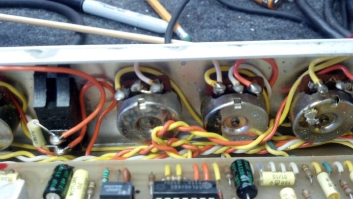
Most of the preamp duties are done with operational amplifiers. Those connectors in a square configuration are for the reverb tank and pedals.
.
This unit is very well built and maintained.
.
Can you see the problem? The pair of transistors on the pink heat sink form a phase inverter that drives the output tubes. In the 1970s, televisions, ham radio gear, and other consumer electronics were commonly built using ‘hybrid’ techniques e.g. solid state parts with power tubes. Leo Fender knew his TV stuff, and applied that technique in his new line of amps.
.
These high powered resistors are part of the phase inverter circuit. They must be matched closely for good performance. Obviously, these are no longer matched.
.
The devices on the heat sink are 75 watt 15 ampere 80 volt power transistors. They should be closely matched for best sonic performance. Also, transistors will drive the next (tube) stage with a bigger voltage swing than two sections of a vacuum tube, because they are inherently lower impedance.
.
The main board is coming out of the chassis so that we can solder and desolder parts.
.
In the late 1070s, circuit board design was performed on computers. Thus, graphical images could be added to the artwork. Also, this circuit board is electrochemically plated tin, which is a fresh new technology not previously seen in Fender products.
.
On a lark, we will measure the value of the remaining 6.8 ohm resistor.
.
It reads a little high. No problem. The resistors will be replaced with a matched pair.
.
The old transistors are coming out for testing.
.
The transistor curve tracer shows that this part is good.
.
The other part is shorted internally.
.
The heat sink is removed and the old resistors are desoldered. Here, we’re cleaning up the circuit board where the resistors go.
.
These two parts were sourced from new stock and selected because their value matches better than 0.1%.
.
These transistors were sourced from new stock and were matched on the curve tracer. See the new resistors above and to the left?
.
The solid state phase splitter drives the tube stage as it should.
.
The tubes are in and it’s time to fire it up!
.
This amp comes with the official MusicMan pedal, controlling reverb and distortion.
.
When a function is selected, the LED comes on. This is nice on a dark stage!
Andy found a ‘beater’ Silvertone amp on eBay and was curious if it could be restored. At first look, it was pretty rough. But could the Unbrokenstring Crew work some magic to undo the damage caused by UPS and previous amp techs?
.
Danelectro built these amps for mail order distribution. In the 1960s, Amazon was a river in Brazil and the Internet was a military thing. But the Sears Catalog brought you nearly anything you wanted.
.
The Sears catalog number was the URL of merchandise. With that number, the world was your oyster.
.
The split splined shaft on the reverb was broken, and the original knob was long gone. The control does work electrically, but the reverb function was not functioning. Or something like that.
.
The main volume knob was missing, because the split shaft was compressed and didn’t have enough remaining ‘bite’ to retain the knob. This could be repaired.
.
One of the preamp tubes is a Chinese 12AX7. That tube tested bad.
.
However, the rest of the tubes were in fine shape and were kept in service. By the looks of the power transformer, I believe that this amp was dropped on its end, because the transformer is leaning to the right.
.
One of the preamp tubes is original, a Silvertone 6FQ7, made in U.S.A.
.
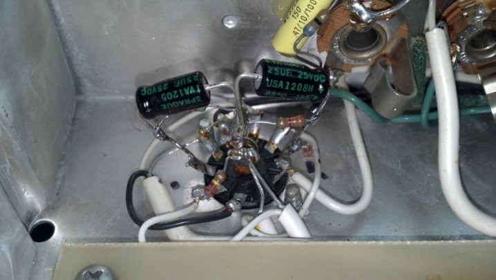
The chassis is hand-wired. We are starting at the preamp section. Those brown capacitors are mica capacitors. Wherever two of them are next to each other, they are taped to each other using black electrical tape.
.
The pilot light is good. The red and blue wires to the right are all shielded signal cables. Power wiring is on the left.
.
The transformer on the left is an interstage coupling transformer. Masonite, a pressed fiber board material, is used extensively in this unit. Here a big chunk runs right down the center of the amp chassis, and many terminal strips are riveted to the Masonite for mounting components.
.
The red cylinders are the filter capacitors, and the small silver cylinders are the power rectifiers. Amazingly, the filter capacitors required almost no reforming. Normally, capacitors this old are replaced out-of-hand, but the owner preferred to keep it as original as possible.
.
Each and every capacitor was screened for leakage at working voltage and capacitance value. Do you see the scorch mark?
.
At this end, we can barely see the output transformer, which has been replaced with a service spare part. Apparently the output transformer failed at some point, leaving some scorched areas behind.
.
These blue wires come from the non-functional reverb tank.
.
These wires come from the other end of the reverb tank. So we can guess that the reverb tank failed, and some Jake Leg tech just cut it out of the circuit rather than fix it.
.
So, we will fix it. Note the duct tape holding the whole arrangement together.
.
We find more Masonite under the tape. Each end of the spring in the reverb tank is stretched between the end clips.
.
A second point of contact intersects the spring about an inch away from the end. Note that this contact is bent. This is another indication that the amp was dropped on its end.
.
In the middle of the spring, this wire guys the spring at the center of the tank.
.
So we bend the bent contact so that it pokes into the spring where it belongs. A very high voltage signal, over one hundred volts, is applied to the contacts at one end. The insulating cardboard on each contact keeps the current from flowing through the spring. However, the high electric field induces a mechanical motion into the spring, which is carried through the spring and wiggles the two contacts at the other end. The wiggling contacts act as a variable capacitor. The change in capacitance causes a varying voltage to be produced, which is amplified and sent to the amp. A moving ribbon microphone or condenser microphone works the same way.
.
Simple enough, huh? Speaking of simple, we have Upgraded this reverb tank from duct tape to wire ties. Which is kind of a big deal, if you ask me.
.
The reverb tank lives here. But the chassis is filthy. Now is the time to clean it all up.
.
A rag is soaked with a combination of solder flux remover and furniture polish, which is tough enough to cut through six decades of crud.
.
The reverb tank is suspended over the chassis with this bracket. It just bolts on.
.
A replacement control has arrived. These stamped sheet metal nuts are used to keep the controls in place. The controls are all recessed behind a trim panel. The recessed trim panel makes it a challenge to find knobs that will work on this amp, as we will find out later.
.
Here, the replacement control has been lubricated and will be wired into its new home.
.
The reverb control has an ON/OFF switch that literally disconnects the reverb tank from the rest of the amp. The two terminals on the back of this control are the ON/OFF switch terminals.
.
That sheet metal nut will not take much torque, so it is being tightened by hand.
.
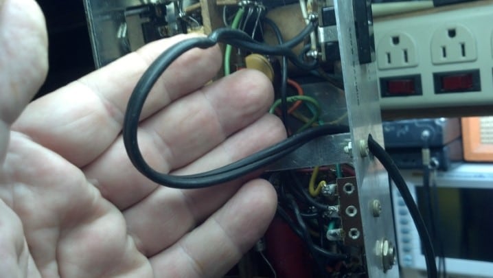
Next, we will replace this two wire line cord with a three wire cord, so no one will be electrocuted if the power transformer insulation fails.
.
Two of the line cord wires go to this convenience outlet. The outlet will remain in place, but will be removed from the circuit.
.
The power switch wiring is being modified to switch only the ‘hot’ wire. The neutral and ground wires will not be switched, per UL requirements. Also, the ‘death’ cap will be removed from the circuit, so that, when it fails shorted, raw 120VAC will not be connected to the chassis. You will find that important if you are holding the guitar at that moment…
.
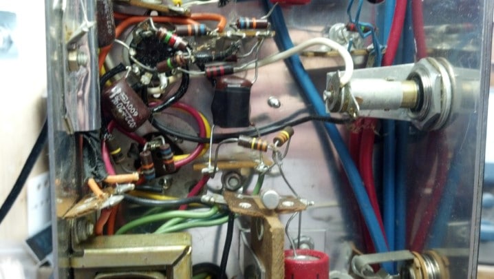
Let’s see what we can do about wiring in the reverb tank. These blue twisted wires are snaked through the chassis and will be attached to the terminal strip in this picture. Here is another good look at a pair of mica capacitors taped together.
.
The little terminal strip in the middle of the picture has the remnants of the original blue reverb tank wires left from where the previous tech disconnected the reverb tank. So now we know right where to reattach them.
.
Another reason to love eBay is that, from time to time, the Correct knobs can be located. These were surprisingly affordable. Some of the original knobs were repaired with Super Glue and reinstalled.
.
The unit is back together and ready for final test!
.
Finally, the Correct knobs really improve the cosmetics of this fine old amp head. The owner wanted to leave the film of rust on the front of the unit, for that Vintage Mojo look. This head sounds fantastic, but the piezo electric reverb tank sounds like something from a Star Trek special effects soundtrack, which, might be just the sound you want!
Texas Amplification, operated by the late Darryl Shifflett, built some of the finest Fender Blackface clones available. Much of the inventory of Texas Amplification was subjected to the flood waters of Hurricane Harvey. This newly-completed combo amp was high enough to escape immersion, but did not escape the subsequent rain, humidity and condensation. Could the Unbrokenstring Crew make this new unit like-new again for its new owner?
.
The nickel plated feet and corner hardware are new, but a light coating of rust from the screws has leached onto the hardware. The Tolex covering appears to be unaffected by the water.
.
Here’s a close-up of the rust. Not a big deal, but this triggers my OCDC (like obsessive-compulsive disease with a bit of AC/DC tossed into the mix.)
.
The back panels of the amp are held on with the Correct screws, but they are showing signs of iron rust as well.
.
This back panel is plywood. It had been wet but had been slowly drying out and was no longer warped. Surprisingly, the Tolex covering was still glued in place.
.
This bit of Tolex covering, however, had become unglued.
.
The Jensen loudspeaker was high and dry, but we’ll check it for any damage.
.
The loudspeaker is more-easily inspected by removing the baffle board.
.
With the baffle board out, it’s easy to verify that everything is in good shape.
.
More importantly, no apparent water damage had occurred here! The Unbrokenstring Crew is fairly certain that this amplifier was at least partially submerged at the height of the flooding. This loudspeaker and grille cloth appear unaffected!
.
Rust Biox is a tool of the museum curator. When old objects are carefully cleaned and restored for display in a museum, such as old weapons or other artifacts, Rust Biox slowly removes iron rust while preserving the un-oxidized material under the rust. This was once sold in the United States as an automotive rust remover, but did not become a ‘hit’ and was removed from the market. The Unbrokenstring Crew, however, is just cool enough to have a source.
.
After each item is processed with Rust Biox, a water rinse and hot air dry prepares it for re-use.
.
The feet of the unit are nickel-plated steel over a rubber bushing. Here, the bushing is separated from the metal foot for processing.
.
These screws hold the feet onto the bottom of the amplifier cabinet.
.
The metal feet are restored. Next, the Rust Biox will remove the rust stains from the rubber feet.
.
Interestingly, this line may have been the ‘high water mark’ and so this unit could have been partially submerged. Furniture polish will clean and condition the Tolex covering to like-new condition.
.
Heat from the hot air pencil softens the Tolex adhesive. The hot Tolex is pressed into place and allowed to cool.
.
The hot air pencil has done the trick! This cabinet appears to have never been wet.
.
The electronics are brand new, with no signs of water damage or corrosion.
.
The Fender Vibro Champ is a single-ended Class A design, a low-parts-count, simple-to-build amplifier with surprising response and tone.
.
All magnetics used in Texas Amplification products are procured through Mercury Magnetics. Top-of-the-line!
.
The violet jewel in the pilot light tells us that we are ready for business!
.
All back together, this amp is running a four-hour-long burn-in to verify that it is 100%. …And dry out anything still wet. This unit was delivered to its new owner, who promptly placed it in his recording studio.
This unit came in to the shop with intermittent signal and power issues. First, we need to get this unit functioning consistently. Only then is it possible to find other issues that need attention. Could The Unbrokenstring Crew have a look at it and bring it back to its full potential?
This all-tube unit looks too new to have any problems at all. Sure enough, it did not power-on as it should. Let’s take a look at this unit before we open it up.
.
Many features are packed into this little guy. And I love the color!
.
Bringing out the Send and Return functions adds versatility when using effects. And there are plenty of jacks for connecting speaker cabinets.
.
The Name/Rank/Serial Number picture helps when ownership changes. The Unbrokenstring Blog has already identified one piece of stolen gear.
.
Remove-able IEC line cords are always nice. But how do we set the AC line voltage? I see an ink mark, but no switch.
.
When we pull the case off, we are greeted with a pleasant sight of all tubes (and solid state rectifiers under the chassis.)
.
Cruising around the sides, we find something of interest!
.
Here is the switch to set the AC mains voltage. D’oh!
.
Other than the fact that the tube sockets are soldered to the PC board, there is very little to dislike regarding the design and layout of this unit.
.
The power supply section appears to be in good condition. The solid state rectifiers are to the left and up from the green PASSED sticker.
.
From left to right, we see the ON/OFF switch and the power level setting switch, the pilot light, volume control, and the bass tone control.
.
Picking up again from the bass tone control, we see the MID tone control, treble tone control, and the GAIN knob.
.
Next to the GAIN control is the input jack. These jacks switch signals when no plug is inserted, so we need to check the operation of all these jack switches once the unit is operational.
.
The power fuse looks good, if not a little saggy. We should check it electrically.
.
Well, what do you know? This fuse has been storing up a lot of Ohms; in fact, over two million ohms (which is more than my meter will measure.)
.
This spade connector has come loose. It could account for this unit not working, as well as the fact that the fuse had open-circuited and begun accumulating all those Ohms…
.
These switching jacks are the source of the intermittent audio. They are all cleaned with DeOxIt and cycled several times to renew them.
.
After a new fuse and after cleaning the switching jacks and reattaching the loose wire, this unit is 100%.