Sophie’s aunt wanted to do something to further her niece’s continuing education and eventual career in music therapy. This nice Luna ukulele was a thoughtful gift. Unfortunately, there were many dead notes. Could the Unbrokenstring Crew bring those notes back to life?

Inside the bag is a ukulele, some picks, a tuner, and an instructional DVD!

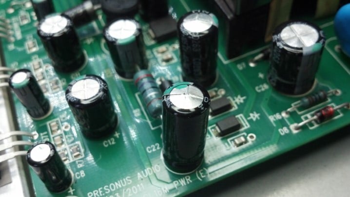
The words for “Peace” in forty-four languages are engraved into the soundboard of this instrument. All you hippies will recognize the peace sign in the sound hole.

Sure enough, there are several notes on the fret board, near the nut, that are muted out.

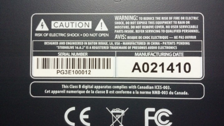
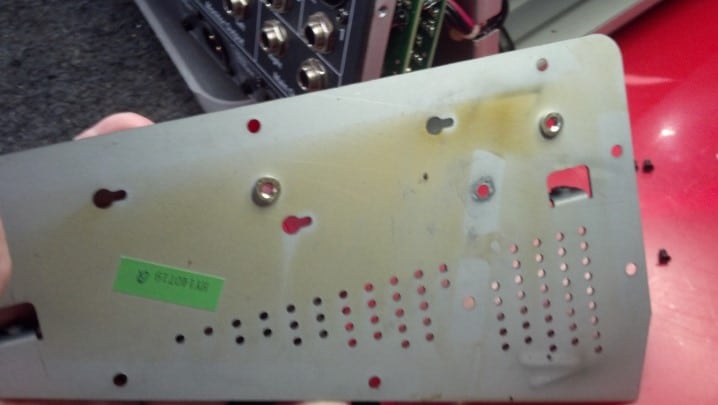
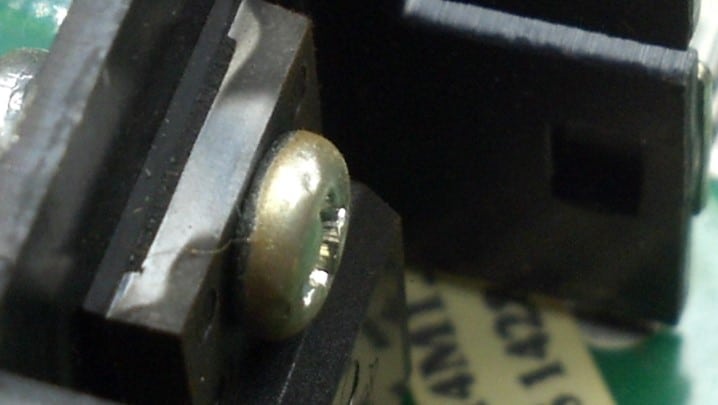
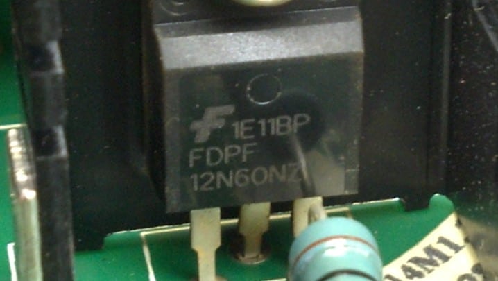
Name, rank, and serial number, please.

I am not sure what this number is…

The fret rocker shows a very tiny difference in fret height, when checking between adjacent frets.

However, a straight edge reveals that the neck is back-bowed. The tape just keeps the machinist’s scale upright so I could take the picture.

I recorded the string height for all posterity. This is not far from right for a ukulele. Some authorities say it’s too high, others say too low. Whatever.
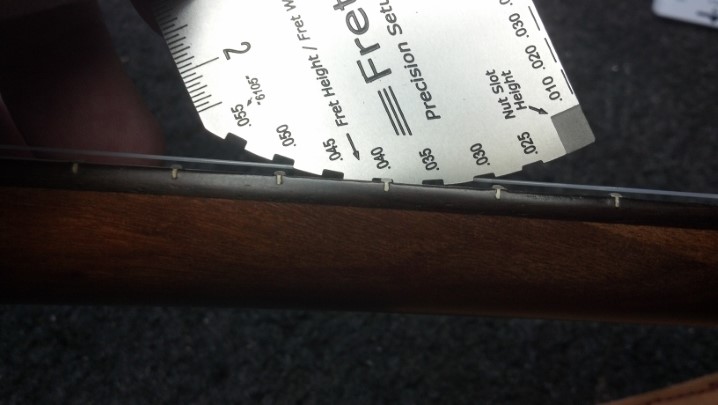
The fret wire height is not adequate to support a fret level job. The back bow is just too much. Yes, the back bow is more than 0.040 inch on each end of the fret board!
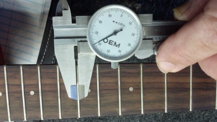
My guess is, the fret board will need to be reshaped. Here, I’m recording the width of the fret wires.

Concert ukuleles are tuned A – E – C – G, with the bottom string, sometimes called String 1, the highest pitch. This G string diameter is about 0.022 inch.

The C string is about 0.030 inch.

The E string is the largest, measuring about 0.035 inch.

The drone string is tuned to A above the G. This string measures about 0.025 inch.

Interestingly, the fret board has about a 20 inch radius, while the nut and saddle are absolutely flat. The Luna Guitars Web site specs this instrument with a flat fret board, too. I’ve decided to re-flatten the entire fret board. The nut must come off. Here, I’m cutting the finish so that the nut can be removed cleanly.

I love whacking musical instruments with a hammer. I find it strangely satisfying.

The saddle slips out of its slot. You can see that there is no radius in the saddle at all.

The Smoking Gun. There is not enough string tension in the world to straighten this neck. It also has a twist. It doesn’t matter that this instrument has no truss rod because it wouldn’t help.

Visually, we can see the wavy fret board and a clear radius. How did this instrument leave the factory?

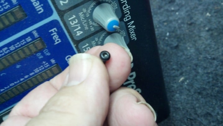
Let’s get the tuners out of the way.

I made this fret remover from an inexpensive set of end nippers from Harbor Freight.

These frets over the body are easily removed.

Before the woodworking begins in earnest, let’s tape everything off.

Some cardboard protects the entire soundboard.
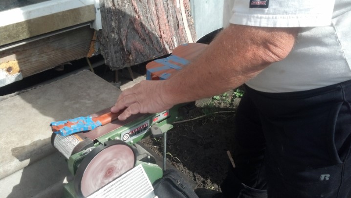
The strategy is to flatten the fret board on the belt sander.

This little belt sanding station came from Harbor Freight.

Some of the safety covers were removed to enable the instrument to set flat on the sanding belt. Do not attempt this at home, kids!

The eighty-grit sanding belt begins to make an impression on the fret board. This fret board appears to be rosewood, but the Web site says that this instrument is all mahogany. Dunno about that.

With a twist that bad, we can easily inspect our progress.

Now I am wondering what I got myself into.

Back to it! Many thanks to my wife Glenda for taking these pictures.

Serious amounts of sanding dust are produced, so we are outside today.

Another check shows that we are not there yet.

The sanding belt is doing its work.

What is it going to take to get this straight?

Sanding dust is going everywhere. No scorch marks yet!

I am pleased that the fret markers are still intact.

Very light pressure is used now to clean up the surface.

Now we’re getting somewhere.

Continuing on, producing sanding dust like crazy.

Now I’m thinking that I need to be careful not to go too far.

Most of the fret board is flat. There is still some fall-away over the body of the ukulele, which is OK with me.

Last few strokes on the belt.

The twist is gone and most of the fret board is absolutely flat. I thought that the noise of sanding would drive the cats away, but we see Jack on the bottom step in the lower left corner of this picture.

The luthier’s scraper shows that the fret board is flat.

The sharp scraper is an excellent tool to finish raw wood.

The fret slots at fret six and seven are almost gone. I really don’t think that this fret board is mahogany.

Fret slot ten is almost gone.

One end of the fret slots over the body IS gone. Yes, it was that bad.

My fret saw was set to 0.054 inch, which is the depth of the new fret tangs.

Every slot was taken down to about 0.055 inch.

These short sections of small fret wire are perfect for this instrument.

Each fret was installed, and nipped to length after installation. The long ends were the pieces at the end of the short strips that weren’t long enough to fill another fret. They get nipped off separately.

After nipping, this file embedded in a block of nylon files the fret ends 90 degrees to the fret board. Moving the file to another slot allows the fret crowns to be filed to a 60 degree angle to the fret board. I love eBay!

Checking for flatness, these frets are ABSOLUTELY flat, which is not surprising.

The fret ends are shaped and burnished by hand, and the fret wires are lightly sanded. As with a classical guitar, the frets are not polished, but finely sanded in the same direction as that of the string.

The original nut was reused, and re-slotted to restore the original 0.060 inch string height. The nut was just right as it was. The fret board was oiled. New strings complete the job. All the notes are present and accounted for!
Thanks for reading all the way to the end!
CONTACT – David Latchaw EE
281-636-8626