Fender Vibro Champ Combo Amp ‘Almost’ Lost to Hurricane Harvey

Texas Amplification, operated by the late Darryl Shifflett, built some of the finest Fender Blackface clones available. Much of the inventory of Texas Amplification was subjected to the flood waters of Hurricane Harvey. This newly-completed combo amp was high enough to escape immersion, but did not escape the subsequent rain, humidity and condensation. Could the Unbrokenstring Crew make this new unit like-new again for its new owner?

.

The nickel plated feet and corner hardware are new, but a light coating of rust from the screws has leached onto the hardware. The Tolex covering appears to be unaffected by the water.

.

Here’s a close-up of the rust. Not a big deal, but this triggers my OCDC (like obsessive-compulsive disease with a bit of AC/DC tossed into the mix.)

.

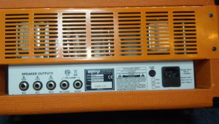
The back panels of the amp are held on with the Correct screws, but they are showing signs of iron rust as well.

.

This back panel is plywood. It had been wet but had been slowly drying out and was no longer warped. Surprisingly, the Tolex covering was still glued in place.

.

This bit of Tolex covering, however, had become unglued.

.

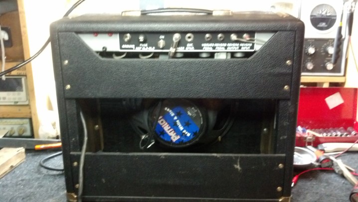
The Jensen loudspeaker was high and dry, but we’ll check it for any damage.

.

The loudspeaker is more-easily inspected by removing the baffle board.

.

With the baffle board out, it’s easy to verify that everything is in good shape.

.

More importantly, no apparent water damage had occurred here! The Unbrokenstring Crew is fairly certain that this amplifier was at least partially submerged at the height of the flooding. This loudspeaker and grille cloth appear unaffected!

.

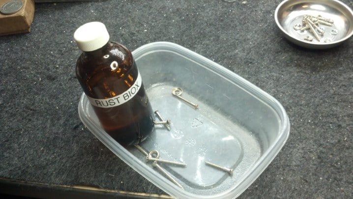
Rust Biox is a tool of the museum curator. When old objects are carefully cleaned and restored for display in a museum, such as old weapons or other artifacts, Rust Biox slowly removes iron rust while preserving the un-oxidized material under the rust. This was once sold in the United States as an automotive rust remover, but did not become a ‘hit’ and was removed from the market. The Unbrokenstring Crew, however, is just cool enough to have a source.

.

After each item is processed with Rust Biox, a water rinse and hot air dry prepares it for re-use.

.

The feet of the unit are nickel-plated steel over a rubber bushing. Here, the bushing is separated from the metal foot for processing.

.

These screws hold the feet onto the bottom of the amplifier cabinet.

.

The metal feet are restored. Next, the Rust Biox will remove the rust stains from the rubber feet.

.

Interestingly, this line may have been the ‘high water mark’ and so this unit could have been partially submerged. Furniture polish will clean and condition the Tolex covering to like-new condition.

.

Heat from the hot air pencil softens the Tolex adhesive. The hot Tolex is pressed into place and allowed to cool.

.

The hot air pencil has done the trick! This cabinet appears to have never been wet.

.

The electronics are brand new, with no signs of water damage or corrosion.

.

The Fender Vibro Champ is a single-ended Class A design, a low-parts-count, simple-to-build amplifier with surprising response and tone.

.

All magnetics used in Texas Amplification products are procured through Mercury Magnetics. Top-of-the-line!

.

The violet jewel in the pilot light tells us that we are ready for business!

.

All back together, this amp is running a four-hour-long burn-in to verify that it is 100%. …And dry out anything still wet. This unit was delivered to its new owner, who promptly placed it in his recording studio.

.

Thanks for reading all the way to the bottom!

CONTACT – David Latchaw EE
281-636-8626

A Little TLC for an Orange Amplification 15 Watt Head

This unit came in to the shop with intermittent signal and power issues. First, we need to get this unit functioning consistently. Only then is it possible to find other issues that need attention. Could The Unbrokenstring Crew have a look at it and bring it back to its full potential?

This all-tube unit looks too new to have any problems at all. Sure enough, it did not power-on as it should. Let’s take a look at this unit before we open it up.

.

Many features are packed into this little guy. And I love the color!

.

Bringing out the Send and Return functions adds versatility when using effects. And there are plenty of jacks for connecting speaker cabinets.

.

The Name/Rank/Serial Number picture helps when ownership changes. The Unbrokenstring Blog has already identified one piece of stolen gear.

.

Remove-able IEC line cords are always nice. But how do we set the AC line voltage? I see an ink mark, but no switch.

.

When we pull the case off, we are greeted with a pleasant sight of all tubes (and solid state rectifiers under the chassis.)

.

Cruising around the sides, we find something of interest!

.

Here is the switch to set the AC mains voltage. D’oh!

.

Other than the fact that the tube sockets are soldered to the PC board, there is very little to dislike regarding the design and layout of this unit.

.

The power supply section appears to be in good condition. The solid state rectifiers are to the left and up from the green PASSED sticker.

.

From left to right, we see the ON/OFF switch and the power level setting switch, the pilot light, volume control, and the bass tone control.

.

Picking up again from the bass tone control, we see the MID tone control, treble tone control, and the GAIN knob.

.

Next to the GAIN control is the input jack. These jacks switch signals when no plug is inserted, so we need to check the operation of all these jack switches once the unit is operational.

.

The power fuse looks good, if not a little saggy. We should check it electrically.

.

Well, what do you know? This fuse has been storing up a lot of Ohms; in fact, over two million ohms (which is more than my meter will measure.)

.

This spade connector has come loose. It could account for this unit not working, as well as the fact that the fuse had open-circuited and begun accumulating all those Ohms…

.

These switching jacks are the source of the intermittent audio. They are all cleaned with DeOxIt and cycled several times to renew them.

.

After a new fuse and after cleaning the switching jacks and reattaching the loose wire, this unit is 100%.

Thanks for reading all the way to the end!

CONTACT – David Latchaw EE
281-636-8626

Marshall JCM900 Tune Up

This wonderful old Marshall JCM900 lives in a recording studio. It was due for a set of tubes and a million-mile checkup. Could the Unbrokenstring Crew refresh this head and resolve the tiny issues that had arisen over the years?


In simple terms, this head has two channels that share a common tone stack, effects loop, and reverb tank. The amount of reverb, as well as the gain and volume, are independently adjustable.


Name, rank, and serial number, please.


The effects loop is accessible from the back. This unit is recording-friendly, with outputs for ‘wet’ and ‘dry’ signals.


The Business End. This amp can be switched to 50 or 100 watt output power.


Two fuses are used in the high voltage plate supply for this amp, which is a nice touch and will add something to the story later. IEC mains power socket and a line fuse rounds out the rear panel.


These power tubes have pushed billions and billions of electrons around, and some of those electrons have interacted with the inert gas inside the glass envelope. Do you see the frowning face in the upper insulator? The brown scorch mark is his beard.


These great tubes have delivered a long service life and are now just about worn out.


Interestingly, Marshall delivered these heads with 5881 tubes, a military 6L6. Later 6L6GCs dissipate more power and take higher voltages. You can read Internet posts regarding the battles between Marshall in England and American importers; the latter changed the tubes on new amps to 6L6GCs because they believed the 5881s would not last through the warranty period.


And here we have the reverb tank.


A walk through the bottom of the unit shows us the output transformer. The red and black leads to to the reverb tank.


On the left is the preamp circuit board containing the input jack, tone controls, and signal switching. The tube sockets are discretely wired, and on the right is another circuit board handling the effects loop jacks.


More views of the preamp board on the left and the output jacks on the right. Tube sockets are in the middle.


At the lower right side of the output circuit board is the power supply power resistors, rectifiers, and fuses


The large blue items are the filter capacitors. These are in excellent condition and will not be replaced today.


The power transformer and power switches are mounted directly to the chassis.


This blue control sets the idling current (bias) for all four tubes. The current splits thru R28 and R29 to manage a pair of tubes each, part of the 50W/100W power control circuit.


The Unbrokenstring Crew are big fans of DeoxIt products. Here, we have sprayed a little D100 into the cap, and then soaked a pipe cleaner in the solution.


The pipe cleaner works well to clean and recondition each individual octal tube socket contact.


We will also wipe off the pins on the bottom of each tube.


So with the tubes installed and operating into an 8 ohm resistive load, we set the idle current for one pair of tubes. But the two sides don’t match.


Here, I’m using my good Fluke bench meter to confirm that one pair of tubes is idling at 50 milliamps, while the other pair is idling at about 41 milliamps or so. Both meters are in good agreement with the values measured, but I’ll stay with my good Fluke to investigate the situation.


Plate current causes heat to be dissipated in each tube. The V1 and V4 tubes are about 114 degrees C. while idling at about 41 milliamps.


The V2 and V3 pair are a little warmer. These tubes are idling at 50 milliamps. The temperature difference confirms the validity of the different idling currents… but why are they different? They share one transformer winding. We paid big money for matched tubes (which, when swapped around, make no difference…) More work!


Remember seeing separate fuses for plate current on the back of the amplifier? Checking voltage drops in the entire plate circuit, we see that this fuse drops about 0.2 volts across it more than the other fuse. Does that tiny voltage drop make any difference?


The fuse for the V1/V4 pair of tubes measures over half an ohm (meter zeroed for test lead resistance.)


This is the other fuse, for the V2/V3 pair plate circuit.


This fuse measures a tiny bit smaller resistance from end to end. Does this actually account for the higher current?


Sure enough, those voltage drops and differences in resistance accounts for about 10mA difference in plate current. New Fuses, Please!


While we’re at it, we will clean the fuse caps with DeoxIt, just as we did with the tube pins.


And the fuse holders will be similarly cleaned. (Hint – these pipe cleaners are perfect for cleaning other hardware besides your tobacco pipe.)


This line filter capacitor is scorched by a power resistor that was pushed up against it, perhaps a result of rough handling during shipping.


Components that are used on AC power require all sorts of safety certifications, which this part has.


I could probably leave this part in the amplifier, but film capacitors are cheap and if this were my amplifier, I would want it taken care of in a proper manner.


So here is the new line capacitor. The power resistor will be moved away from this guy when it is installed.


The filter capacitors in the bias circuit were also replaced, while troubleshooting the plate current imbalance.


Of course, replacing those parts requires access to the bottom of the circuit board.


While we have the circuit board up and out of the way, we can catch a glimpse of the discrete-wired tube sockets. This is a much better way to wire vacuum tube sockets, rather than solder them to a printed circuit board IMHO, because the tube sockets expand and contract much more than the circuit board material, whereas the discrete wire can just flex with the expansion and contraction.


This little bit of trimmed wire was stuck on the bottom of the circuit board. This will be no issue unless it comes loose, which it might do just as you are ready to go on stage and start the set.


Now this amp is running like a clock. The waveform represents the voltage across eight ohms driven with 110 watts, with a 440Hz sine wave injected into the input jack.


The chassis goes back into the case. I removed the power tubes for this step because I didn’t want to risk breaking anything in case I got stupid. The red and black cables to to the reverb tank.


Everything is checking out!


The sheet metal rear panel is much easier to align when the unit is face-down on the bench.


Zenith televisions were advertised with the slogan “The quality goes in before the name goes on!” After a four hour burn-in, the sticker is affixed on the output transformer side of the rear panel.

Thanks for reading all the way to the end!

CONTACT – David Latchaw EE

281-636-8626

Fender Princeton Reverb Amp is Snatched from the Jaws of Hurricane Harvey

Partially submerged in the flood waters of Hurricane Harvey, this combo amp was rescued when the waters receded.  Could the Unbrokenstring Crew turn this insurance claim into a working unit again?

 At first glance, this unit is in pretty good shape.  Fortunately, the flood waters around this unit were not salty, but fresh rain water.  The grille cloth was not badly stained, and much of the exterior grime was superficial.


Not much damage had occurred to the cabinet; some warpage was beginning to appear in the bottom baffle.  The interior was still wet.  This implied that, if the drying-out process could be controlled, no further damage to the cabinet would be sustained.


Can you see some rust on the screws?


This side has some mold.


The bottom Tolex has some mildew beginning to form.  Look at the rust beginning to form on hardware in the foreground.


The handle was beginning to rust.  This could be managed.


The handle and the Tolex is cleaned and reconditioned with this, which also gives us a clean lemon scent!


This is the top of the reverb tank.  Yes, beads of water, still on the exterior of the tank.


The previous owner had padded the top of the tank with gray foam, and the bottom with cardboard.  The cardboard was soaking wet.


Reverb tanks are inexpensive, so we will just order a new one.


The paper cone of the loudspeaker was intact.  This loudspeaker will be replaced by the new owner.


Moisture inside the amp chassis has swelled the turret board.


Water has reacted with the solder flux, creating a brown crust around all the solder joints.  The components still look pretty good, although they cannot be trusted now.


Corrosion on the tube socket contacts testifies to the presence of liquid water here.  Note also that the zinc plating on the once-shiny chassis is turning cloudy.  This tells us that the zinc is doing its job as a corrosion-inhibiting plating, sacrificing itself to protect the steel underneath.


The cabinet hardware is washed in Rust Biox to clear away the rust.  This chemical is available in Europe, but of course, The Unbrokenstring Crew is just cool enough to have this material here in the U.S.


The nickel plating has very little iron to rust;  This deposit is probably mud.


All the hardware is cleaned up.  The Tolex is cleaned and conditioned with the furniture polish.  The cabinet looks good as new!


A new tube chart is pasted inside the cabinet where the original one was located.


For the electronics, a hand-wired chassis from the estate of Darrell Shifflett of Texas Amplification is pressed into service.  The Unbrokenstring was truly fortunate to buy the remaining inventory of Texas Amplification.  This chassis was part of the inventory.  Look at those shiny new jacks!


The knobs are, of course correct.  This is a clone of a Fender Blackface Princeton Reverb, not built in California but rather in Houston, Texas.


Darrell was a master of the details.  Even the front panel is Correct for this unit.


As a testament to Darrell, let’s just take a look at his workmanship.


The wiring and component placement is meticulous.


If original components were available, such as the carbon composition resistors, he used them.  Modern flame-proof components are used where an improvement in reliability and safety without sacrificing sonic performance justified the upgrade.

Even the wire is period-correct, fabric-covered was used for the point-to-point wiring, just like the originals.


A bias check for EACH output tube is added to the rear panel.  Millivolts measured from red to black correspond to milliamps of plate current.


The jacks and controls are name-brand and not the cheap stuff.


But just look at that fresh brass sheet used for the ground plane under the controls.  The original brass probably didn’t look this good in Fender units when they were new!


The underside of this amp is just a voyage on the Good Ship Eye Candy!


The electronic tremolo circuit is duplicated on this turret board.  Not sure why this turret board is warped, but it is electrically 100%.


Speaking of turret boards, just look at the meticulous care used to mount each component and route the leads.  Even the bias potentiometer is nicely placed.


Comparing this layout against the original Fender drawings is just breath-taking.


I’m really jazzed about how the fabric-covered wire is carefully routed around the tube sockets.


We needed a new rectifier tube for this amp.


Darrell used Mercury Magnetics for all the transformers on this chassis…  the best you can get!


With the power on, all the voltages are correct.


The new reverb tank arrived today.


The bag protecting the reverb tank is dry and ready to be used again.


These straps hold the reverb tank bag in place in the bottom of the amplifier.


The ON/OFF switch works as it should.  Since the AC cord is a modern three-wire unit, the original ‘GROUND’ switch is wired as a STANDBY/ON switch.


This unit is ready to go back to the new owner, who will install the new loudspeaker.  Pretty nice unit for having been under water!

Thanks for reading all the way to the end!

CONTACT – David Latchaw EE
281-636-8626

Peavey MX Combo Amp Rescued from a Bad Amp Tech

This combo amp had lived a hard life and had finally quit.  Grandpa wanted his grandson to get the amp fixed so that they could jam together again.  Could The Unbrokenstring Crew bring this unit back to life?
 We begin with a quick tour of the rear panel.  The ground switch is a tip of the hat to the Old Days of two wire AC.


 The foot switch plugs in where the REMOTE SWITCH jack is coming loose.  This gets fixed.


 I’m surprised that this hadn’t ripped loose.  The whole connector wil be replaced.


 Name, Rank, and Serial Number, please!


 What have we here?  We found grandpa’s stash.


Let’s get this line cord wired correctly.  Do you know what’s wrong?


 The black wire goes under the brass screw. “Black on brass will save you ass.”  You’re welcome.


 The reverb tank connects to the main circuit board with this connector.


 Even after all this time, the high voltage capacitors are still charged.  Woah!  This is my discharge wand at work.


 Our first mystery… where does this nut go?


 This is a fuse.  No, you think that it is a piece of 16AWG wire, but it is a fuse.  Or, it is where a fuse goes.


 And here, someone was tired of the fuses falling out of the holders, or what was left of the holders.


 The heat from the flow of current has wreaked havoc on this solder joint.


 This probably smelled bad when it was hot.


 Now that the introductions are out of the way, we need to start replacing this nonsense.


 These are commercial fuse holders.  These will replace all of the preceding nonsense.


 The plan will be to install these new fuse holders at a spot in the circuit where they will be functional, yet out of the way.


 The new fuse holders are held down with a screw.  This hole is where the screw goes.  Here goes!


 Another hole is drilled for another fuse holder.


 This hole is in the center of a trace.  We won’t miss that copper.  Much.


 Insulating nylon nuts and bolts are used to keep the new fuse holders in place.


The traces in the burned circuit boards are replaced with this Teflon-covered wire.


 Everything is now stuffed back into place.  Not too shabby, if I do say myself.


Turning our attention to the rear panel, your sharp eyes may recognize this connector as a MIDI female panel connector.


 To keep the connector hardware in one place, some of this Thread Locker is all we need.


 We have the original foot switch.  It needs a new cable, with a connector to match what we just installed in the amp.


 This MIDI cable will be repurposed to replace the cable on the footswitch assembly.


 We don’t need this connector.  Instead, this end of the cable will be wired to the switches themselves.


 The new cable is soldered directly to the switches  Note the strain relief installed to the right of the picture..


 This pedal is ready for action once again!


 The amp is reassembled and is ready to go!


 The four hour burn-in test is underway.  I think we have rescued another vintage Peavey amp!

Thanks for reading all the way to the end!

CONTACT – David Latchaw EE
281-636-8626

Crate Vintage Club 30 Recap

Robin had another of these wonderful Crate combo amps for servicing.  The Unbrokenstring Crew knew just what to do!

Robin’s 50 watt combo was serviced earlier, in this blog post: https://www.unbrokenstring.com/crate-vintage-club-50-amp-repair/


This is a 30 watt unit, with very similar construction.  Look at all that St. Louis Music goodness!


The loudspeaker is 100% and made in U.S.A.


This pic just documents where the wires go.


These wires go to the reverb tank.  They are marked with a magic marker so that they can be correctly re-installed.


The tubes need to come out as we are removing the printed circuit board from the chassis.


These numbers correspond to the tube numbers on the schematic.


While we’re here, we’ll make a check of the condition of each of the tubes.


Restoring the washer stack is essential to keep the strains on the printed circuit board to a minimum when reassembled.


So we are now able to remove the main circuit board.


As we did with the 50 watt unit, we are taking this opportunity to clean up the front panel.


Sure enough, the capacitors have reached End Of Life.


This circuit board is now recapped!  Pretty!


After reassembly, this quick check shows us that we can drive 30 watts continuously into eight ohms with no problem!


This unit has an easy bias setting arrangement.  Here, we’re using the 4 1/2 digit Fluke meter to measure current.  The AC power is supplied by the Variac on the shelf.


Some of the cabinet screws were cross-threaded at one time in the past.  So, we can chase them with a die.


The captive nuts are cleaned up with a matching tap.  We’re good for Final Assembly!


Another fine combo amp is ready for the next million miles!

Thanks for reading all the way to the end!

CONTACT – David Latchaw EE
281-636-8626

Peavey Artist Combo Amp Refurb

This Peavey Artist combo amp was WAY too distorted to suit even the most extreme metal head. Could the Unbrokenstring Crew look into this and put this unit back into service?
First, a tour.  You can have two channels, or a mix of the two ‘Automix’ inputs.  This was a ‘thing’ back in the day.


The other controls are straight-forward.


The standby switch is in the front, whereas the AC power on is in the back.  Actually, I like this because if both power switches are in the back, half the time I switch the wrong one.


The AC line duties are all squared away on this side.  The City Of Los Angeles has their own version of UL.  That’s the yellow and red sticker.


The right hand side of the rear chassis has the ins and outs for this amp.


These are all Peavey-branded tubes.  They are all in good shape and will stay in this amp for now.


So we put a clean sine wave in, and this is what we get out.  The positive power supply is weak.


An overall gut shot shows power on the left, preamp on the right, and power amp on the bottom.


These capacitors have begun to swell and push the seals outwards.


We have signs of overheating.  These resistors handle power distribution and are somehow related to our problems.


The other power supply has a cooked resistor as well.


Here I am just documenting all the plugs and wires so I can get them back in the same place.


These capacitors are also bulging and will be replaced.


Time to remove the power supply board and work it over.


This circuit board holds the tube sockets.  We have an intermittent short to ground under this assembly.


At first I thought that the short was under the tip terminals of these jacks, but that was not the case.


I am going to pull this assembly out and look it over as well.  The blue, red, and brown wires are high voltage.


The blue capacitor in the upper right is the ‘death cap.’  If it shorts, 115vac is connected to the chassis.  Not good if you ever touch the amplifier.  Fatal if you touch the amplifier with one hand and grab a microphone with the other hand.


This circuit board is supported by the tube sockets.  All four sockets will be unsoldered.


Out this guy comes.


Here is our short circuit.  These are component leads from parts installed on top of the circuit board and soldered from the top.  I guess if the excess length is out of sight, then it is out of mind.


Here are some of the parts on the top side.  I don’t think these were replaced in the field, but rather it came from the factory with the untrimmed leads.  Sloppy.


However, wires that are too long are easier to deal with than wires that are too short.


I am cleaning up the bits of crap in the bottom of the chassis, using some sticky tape as a way to capture the crap.


I have installed new bleeder resistors and new capacitors on this assembly.  That big blue resistor is a high voltage dropping resistor.  This part is fine and will not be replaced.  However, those are not made anymore, and I have some of the last remaining stock of the OEM resistor.  You’re welcome.


Everything gets trimmed and cleaned up before reassembly.


The power supply board has new caps everywhere.


The Ty-Wrap was my idea.  These big parts need some mechanical support, but I’m not big on lots of hot glue.


The original power resistors were way out of spec, so these new parts are higher wattage to take the abuse.


These caps on the preamp board were replaced.


As was this guy.


These were the overheated resistors that we saw earlier.

These new resistors are actually more robust than the parts they replaced.  And they are flame-proof.


We are back on the air!

Thanks for reading all the way to the end!

CONTACT – David Latchaw EE
281-636-8626

Ampeg V4B Bass Amp Refurbishment

This wonderful old Selmer-era Ampeg bass head was pulled out of its retirement in the closet and put back into service.  But it had a few issues to address, so that it could reliably pump out the tones that is the Ampeg Experience.


01V4B the patientThis unit appears to be absolutely factory stock.  The Houston humidity has had an effect on the aluminum faceplate.

02V4V rear pnl1Taking a tour of the rear panel, we see a bracket upon which the line cord may be wrapped.

03V4B rear pnl2The convenience outlet is a three-prong unit, which is nice.  The hum balance control adjusts the bias current in the output tubes to be the same.

04V4B rear pnl3Magnavox owned both Selmer and Ampeg for a while, if I recall correctly.  Note the tube layout information.

05V4B rear pnl4Here is the other bracket for the cord, and the output jacks and impedance switching.

06V4B cordDude, are you still smoking?

07V4B internals1This is a nice intersection between hand wiring and the use of an etched circuit board.

08V4B internals2This cap and the bleeder resistors are slated for replacement.

09V4B cap1Yes, you can still get multi-section capacitors if you shop diligently.

10V4B cap2The prongs of the new capacitor need to fit in the slots in the chassis.

11V4B cap3There is plenty of height inside the chassis, but it doesn’t hurt to document what we have.

12V4B cap4Likewise, we’re documenting what we have.

13V4B cap1Here is the new multi-sectioned filter capacitor and the hole where it goes in the background.

14V4B cap2The outer can of all of the capacitors is isolated from the chassis, so these green fiberglass spacers are used under the capacitor.

15V4B cap3I think we’re done here!

16V4B cap4The new cap looks nice on the top of the chassis.

17V4B cap3The axial filter capacitor will be replaced with this part.  I am forming the leads to appear in a manner similar to the original part, seen above.  A little Teflon insulating tubing helps keep the electricity under control.

18V4B cap4Wires will be attached to the terminals, so the leads are formed into a loop to accept the wires.

19V4B cap5The wire bending is done with a hand-tool called “chain nose pliers.”

20V4B cap6The original part has a mounting ring around it.  We will need to recycle this mounting scheme to maintain originality.

21V4B cap7The ring is off!  I was a little concerned that I would mess it up, but a little heat was all it took.

22V4B cap8Here is the original mounting ring applied to the new capacitor.

23V4B cap9The ring can slide around just a little bit to give us a nice-looking mounting solution.

24V4B cap10And here we are, all wired up and ready to go back to work.

25V4B good capsThese guys have been replaced recently, and they check out as new.  So, they will remain in service.

26V4B controlsSome of the front panel slide switches were dirty, so some cleaner and lubricant were sprayed into them.

27V4B top1Now that the caps are changed out, let’s look at the top of the chassis.  The output transformer and output tubes are on the left side of the chassis.

28V4B top2The preamp tubes and power transformer are at the right end of the chassis.

29V4B top2detail1The open areas around the tube sockets are a nice touch.  The chassis is steel and very stiff, even with the relief.

30V4B top2detail2More low and medium voltage goodness at the other end of the slot.  Nearly every schematic test point is accessible from the top of the unit without turning it over on the bench.

31V4B Magnavox 12DW7This 6K11 Compactron tube tests very good, with each of the sections closely matched to the others.  Good News!

32V4B inputjax1The input jacks were corroded, so these were changed out with new Amphenol units.

33V4B inputjax2Here is the inside-the-chassis view of the new jacks.

34V4B indicator1The neon indicator for the AC power was functional, but the indicator for the high voltage was not.

35V4B indicator2So, this neon indicator will take its place.  The mounting hole is the same size, but the new part is chrome.  What to do?

36V4B indicator3We scrubbed the chrome ring with steel wool, then applied several coats of black polyurethane paint to the bezel.

37V4B Indicator4Here are both indicators.  The high voltage is amber, and the AC indicator is red, as it was when the amp came from the factory.  The colors are a bit messed-up because of the jpeg processing in the camera…  looks good in Real Life!

38V4B Happy CustomerAnother happy customer picks up his finished bass head!

Thanks for reading all the way to the end!

CONTACT – David Latchaw EE
281-636-8626