Fender Blues Junior Puts On A Light Show

The Unbrokenstring Crew is amazed at the tough life that this tweed Fender Blues Junior has endured. Yes, it doesn’t work at all. Can we bring this poor thing back to life?

.

Brian salvaged this amp from the curb in front of a house in North Carolina while volunteering in the cleanup following Hurricane Florence in 2018.

.

Water damage is clearly evident on the tweed fabric, with stains and mold inside and out. The glue holding the fabric on the amp has failed, particularly on the bottom half of the cabinet.

.

Starting from the bottom up, we use hide glue to stick everything back down. The lacquer coating on the tweed fabric has saved it from completely disintegrating.

.

We are employing hide glue because it is not water based; we don’t want to make the wood cabinet swell any more than it already has. The hide glue can be easily cleaned up afterward, even after it dries, with warm water and a rag.

.

Here, we’re removing the chassis. Fortunately, the rust is not too bad on this chassis.

.

Someone has been here before, and they probably didn’t have a Fender employee badge.

.

Too much heat and rework has destroyed the plated-thru holes in the circuit board. We can repair this.

.

The connections (called ‘nets’ in circuit board parlance) are restored with small bits of stranded copper wire, tinned and soldered in place.

.

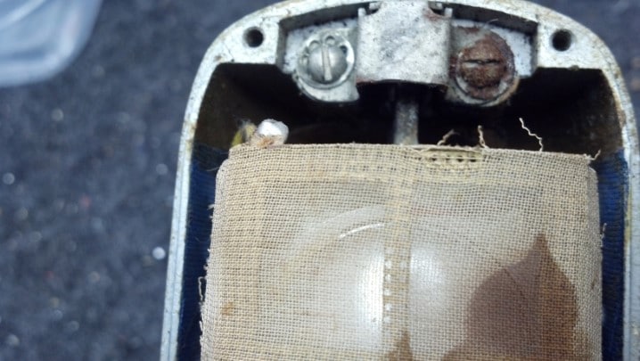
The heart of any tube amplifier is the output transformer. It bridges the gap between high voltage power, tubes, and the loudspeaker. This HiPot (high potential tester) is measuring a complete failure of the insulation between the primary plate circuit windings of the output transformer and the secondary loudspeaker windings. Surprisingly, the loudspeaker is fine!

.

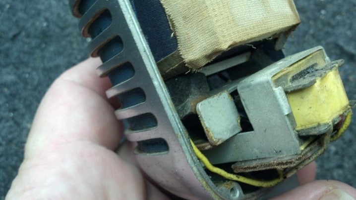
Hidden on the back side of the chassis, the output transformer has lived. And Died. Alone. In The Dark.

.

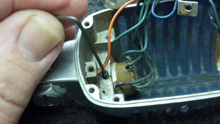
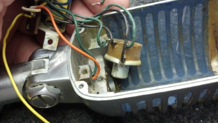
Fortunately, The Unbrokenstring Crew has a supply of original parts for boutique Fender amplifiers and clones, from Texas Amplification stock. This nice example of original Fender iron fits perfectly on this chassis.

.

Testing the 6BQ5 / EL84 tubes, on the other hand, produces a light show. The purple glow is ionized gas inside the tube, and the blue lights hitting the paper behind the tube are beams of uncontrolled electrons.

.

The red filaments are the only colors that should be there. After these pictures were taken, I had to replace the socket adapter on my TV-7U tester because it melted internally. The rest of the tester is fine and was re-calibrated – with a new socket adapter.

.

After the light show from testing the tubes, each section of the amplifier is tested separately, in order to discover any other collateral damage from either the water or the failed output transformer. This amp will be Good To Go once the glue dries!

.Thanks for reading all the way to the bottom!

CONTACT – David Latchaw EE
281-636-8626

Fender Blackout Strat Becomes Even More Classic(al)

The original neck on this MIM Black Strat was made from wood that tended to twist when the string tension varied, either because of temperature changes or when employing different string gauges. It’s now time to take this guitar to the next level, and make it an iconic Blackout Strat

.

The neck will be retired to another instrument.

.

This instrument was built in 2006, which happened to be the 60th anniversary of the founding of Fender Corporation.

.

The neck is off and headed to its new home.

.

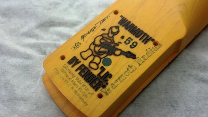
David Gilmour’s Blackout Strat has a maple fret board. This instrument will get a new maple neck, with a 59 ‘C’ contour and an almost 2 inch wide nut. With light strings, this guitar will feel like a nylon-stringed classical guitar.

.

The aftermarket Fender tuners are lined up with the machinist’s rule and tightened into place one by one.

.

These tuners are ‘locking’ tuners, which positively grip the end of each string in a clamp. This is necessary on this instrument because of the very light gauge strings we will be using.

.

Head stock and nut are ready to go.

.

The middle pickup appears to be not working. Let’s take a look inside.

.

Sure enough, there is a broken wire inside the pickup cover.

.

The break in the wire is literally in the very last turn! So one turn is un-spooled and threaded through the eyelet where it belongs.

.

As was done at the factory, the wire end is pulled through the eyelet a few times and soldered in place.

.

The middle pickup is tested and is right where it should be.

.

The Classic(al) Blackout Strat is strung with 7 gauge strings; Yes, not 12s, not 10s, but with Billy Gibbon’s own Dunlop Reverend Willy Extra Light Electric Guitar Strings, .007-.038. With the proper setup, this instrument has the play-ability and feel of a nylon-strung classical guitar. Thus, we have the Classic(al) Blackout Strat.

.


Thanks for reading all the way to the bottom!

CONTACT – David Latchaw EE
281-636-8626

Fender Vibro Champ Combo Amp ‘Almost’ Lost to Hurricane Harvey

Texas Amplification, operated by the late Darryl Shifflett, built some of the finest Fender Blackface clones available. Much of the inventory of Texas Amplification was subjected to the flood waters of Hurricane Harvey. This newly-completed combo amp was high enough to escape immersion, but did not escape the subsequent rain, humidity and condensation. Could the Unbrokenstring Crew make this new unit like-new again for its new owner?

.

The nickel plated feet and corner hardware are new, but a light coating of rust from the screws has leached onto the hardware. The Tolex covering appears to be unaffected by the water.

.

Here’s a close-up of the rust. Not a big deal, but this triggers my OCDC (like obsessive-compulsive disease with a bit of AC/DC tossed into the mix.)

.

The back panels of the amp are held on with the Correct screws, but they are showing signs of iron rust as well.

.

This back panel is plywood. It had been wet but had been slowly drying out and was no longer warped. Surprisingly, the Tolex covering was still glued in place.

.

This bit of Tolex covering, however, had become unglued.

.

The Jensen loudspeaker was high and dry, but we’ll check it for any damage.

.

The loudspeaker is more-easily inspected by removing the baffle board.

.

With the baffle board out, it’s easy to verify that everything is in good shape.

.

More importantly, no apparent water damage had occurred here! The Unbrokenstring Crew is fairly certain that this amplifier was at least partially submerged at the height of the flooding. This loudspeaker and grille cloth appear unaffected!

.

Rust Biox is a tool of the museum curator. When old objects are carefully cleaned and restored for display in a museum, such as old weapons or other artifacts, Rust Biox slowly removes iron rust while preserving the un-oxidized material under the rust. This was once sold in the United States as an automotive rust remover, but did not become a ‘hit’ and was removed from the market. The Unbrokenstring Crew, however, is just cool enough to have a source.

.

After each item is processed with Rust Biox, a water rinse and hot air dry prepares it for re-use.

.

The feet of the unit are nickel-plated steel over a rubber bushing. Here, the bushing is separated from the metal foot for processing.

.

These screws hold the feet onto the bottom of the amplifier cabinet.

.

The metal feet are restored. Next, the Rust Biox will remove the rust stains from the rubber feet.

.

Interestingly, this line may have been the ‘high water mark’ and so this unit could have been partially submerged. Furniture polish will clean and condition the Tolex covering to like-new condition.

.

Heat from the hot air pencil softens the Tolex adhesive. The hot Tolex is pressed into place and allowed to cool.

.

The hot air pencil has done the trick! This cabinet appears to have never been wet.

.

The electronics are brand new, with no signs of water damage or corrosion.

.

The Fender Vibro Champ is a single-ended Class A design, a low-parts-count, simple-to-build amplifier with surprising response and tone.

.

All magnetics used in Texas Amplification products are procured through Mercury Magnetics. Top-of-the-line!

.

The violet jewel in the pilot light tells us that we are ready for business!

.

All back together, this amp is running a four-hour-long burn-in to verify that it is 100%. …And dry out anything still wet. This unit was delivered to its new owner, who promptly placed it in his recording studio.

.

Thanks for reading all the way to the bottom!

CONTACT – David Latchaw EE
281-636-8626

Cool Sunn Practice Combo Amp Blows a Fuse

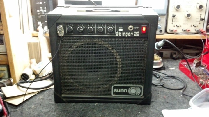
The fuse blew in this Sunn Stinger 20, but the new fuse blew as well. Then, it quit working for good. Cool Under Fire wanted this combo amp back in action. Could The Unbrokenstring Crew sort it all out?


Our patient still has that cool Sunn vibe after all these years, even if it doesn’t work.  That name badge is recognized by all.


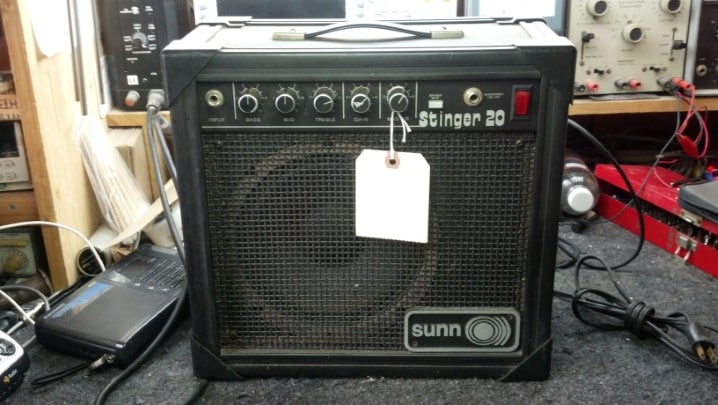
Getting up close and personal to the front panel, we see an input jack and three tone controls.


Independent Gain and Volume controls show that this unit means business!  The mute button and headphone jack give this amp a family-friendly advantage over other inexpensive practice amps.


As is found on many guitar amps, the cabinet is sealed with a closed back.


Oh no!  The sticker says “DO NOT OPEN.”  What are we going to do?


We open it, of course.  How long has it been since you’ve seen a loudspeaker with a square magnet?


Obviously this is a four-ohm loudspeaker.


The steel chassis has circuit boards for the preamp functions, just behind the controls, and power supply and audio power amplifier at the rear of the unit.  Nothing appears out of order here.  No, wait!  Look here!


This wire has come un-crimped from the terminal, seen in the background.


We can just open this terminal up a bit, re-insert the wire, and solder it in place.  But the question remains:  Could this have been the reason that the unit blew fuses before it finally quit permanently?  I don’t think so.


While we’re waiting on a copy of the Sunn Service Bulletins for this amp to come via email, let’s take a minute to clean this unit up.


The controls hold the front edge of the circuit board in place, and a couple of screws hold the back edge steady.


The headphone jack is entirely isolated from the chassis of the unit.  Even though the chassis is wired to the green wire safety ground in the AC cord, taking measures such as this makes the UL Certification easier.


The input jack is shielded from interference with this metal bracket.  This kind of additional shielding is almost never done on inexpensive amps…  this Sunn is definitely a Cut Above!


The switches and controls are easily cleaned now that they are easily accessible, as shown here.  The Unbrokenstring Crew NEVER forces cleaning fluid around the shaft of the potentiometers as a cleaning procedure, because dirt and old lubricant is forced inside the control.  It cannot end well.  Sorry, StewMac.


With all the hardware out of the way, it is a trivial matter to clean up the face plate.  Gibson Guitar Pump Polish is pressed into service for this step.


Reassembly also involves tightening the woodwork.  Over time, wood shrinks (even in humid South Texas) so most amplifier cabinets will develop buzzes and rattles as they age.


Maybe if we work quickly, the “Do Not Remove” police will not catch up to us and put us in jail.


The Service Literature arrived!  It states that the next-higher ampacity of fuse should be used in this unit;  There was an error at the factory wherein units in this serial number range had an inadequate fuse installed!  This little amp has run for hours with no issues!

Thanks for reading all the way to the end!

CONTACT – David Latchaw EE
281-636-8626

Shure 55S Microphone Rescued from the Dumpster

Dr. Shoen’s girlfriend at the time found this microphone in a dumpster behind a church. What did he really find, and could it be more than a theatrical prop onstage? The Unbrokenstring Crew goes to work!


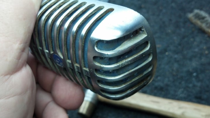
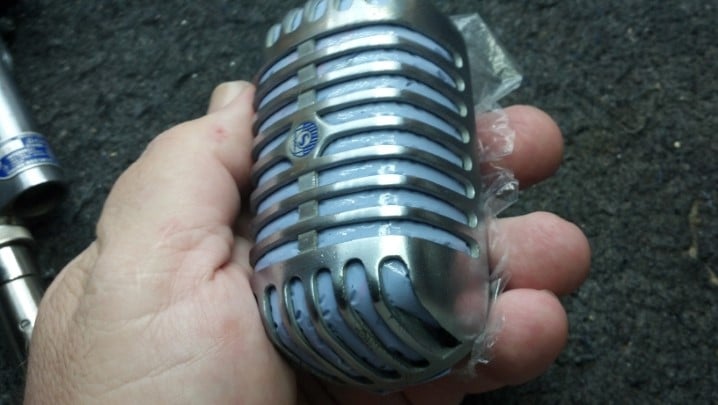
Shure Brothers built this iconic microphone at the factory in Evanston, Illinois in the years between 1951 and 1961. The art deco design is recognized around the world as “The Elvis Microphone.”


The 55S is a smaller version of the Model 55 Shure Brothers microphone first produced in 1939.


Unidyne is a term coined to reflect that a single (unitary) microphone diaphragm is employed. The moving coil technique employed to convert sound pressure into electricity makes this a dynamic microphone; Thus we have the word “Unidyne.”


Units with the ON/OFF switch were produced after 1961


The silk wind screen is badly deteriorated. The microphone makes a loud ‘clunk’ noise when it is moved. We need to look inside.


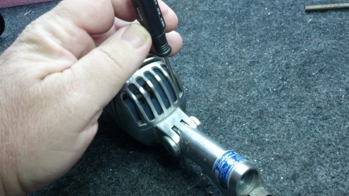
Four screws allow the halves of the microphone body to be separated.


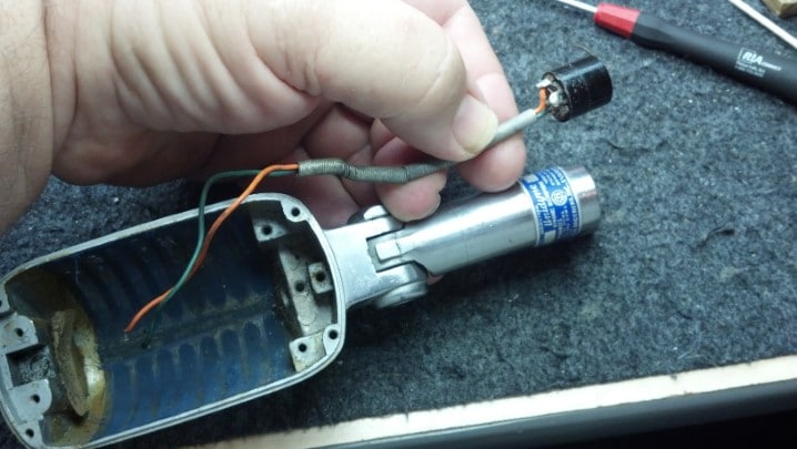
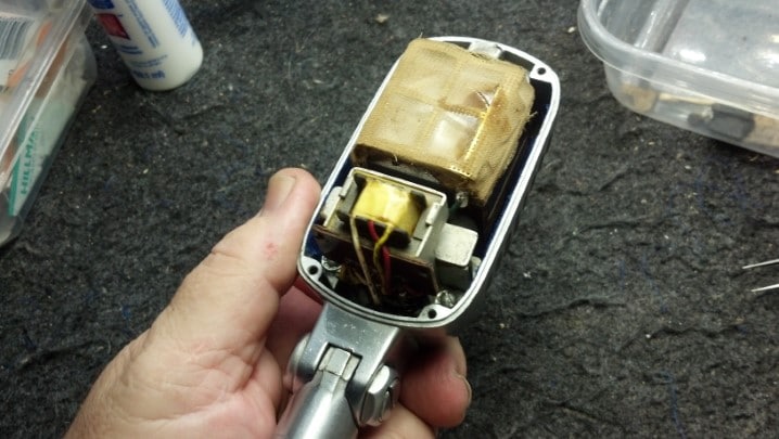
Inside the microphone, we see the element at the top and a multiple-impedance transformer on the bottom.


Two screws hold a bracket that retains a foam vibration dampener in place, which has long since deteriorated and crumbled away. This is the source of our ‘thunk.’


Two more foam vibration dampeners hold the bottom of the element. They are also deteriorated. More ‘thunk.’


The microphone element lifts out easily once the top bracket is removed.


Some of the foam isolation dampeners remain on the bottom two microphone element supports. These are end-of-life and no longer available from Shure.


It is easy to see places where the silk wind screen is missing.


The matching transformer is mounted along with a couple of boxes that retain the now-deteriorated foam vibration dampeners.


Two screws hold these parts in place.


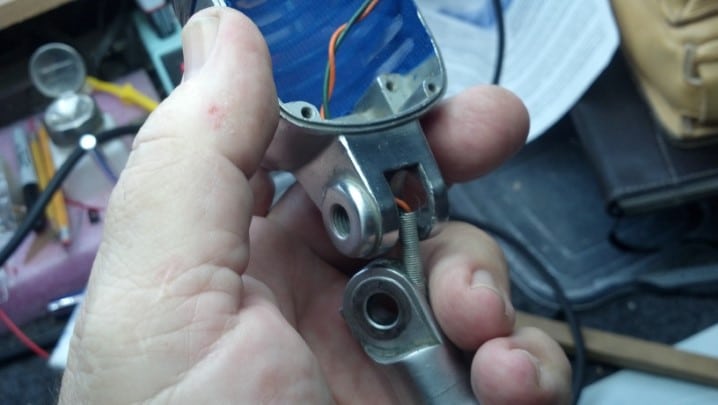
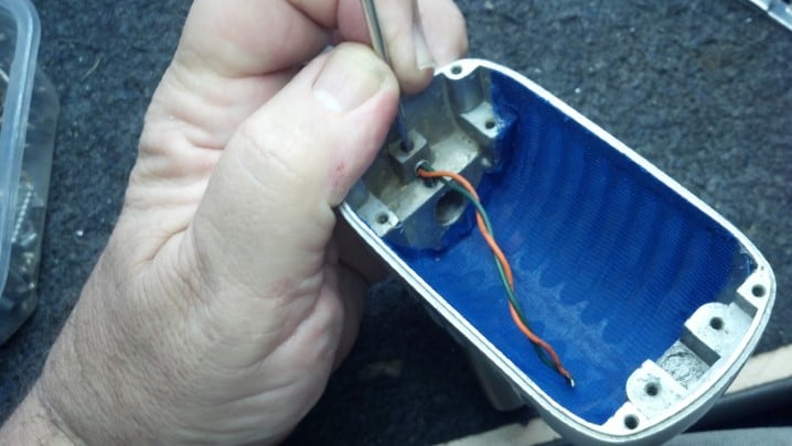
We see the back side of the impedance selector switch in the background, and some set screws in the foreground. What do these do?


The bottom set screw is supposed to hold this spring sheath around the green and orange wires in place.


The top set screw holds the impedance selector switch in place.


We need to take everything out.


The spring sheath runs through the base of the microphone and protects the wires as the microphone is flexed at the joint.


Inside the top of the microphone case we find this sticker, which records the patent numbers employed in the design of this microphone.


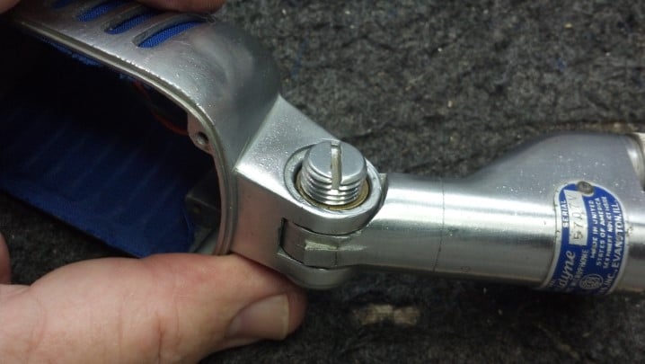
The pivot between the microphone and base needs to come apart for cleaning and adjustment.


This screw can be adjusted to set the stiffness of the microphone head relative to the base.


Graphite washers ride between the moving parts for lubrication.


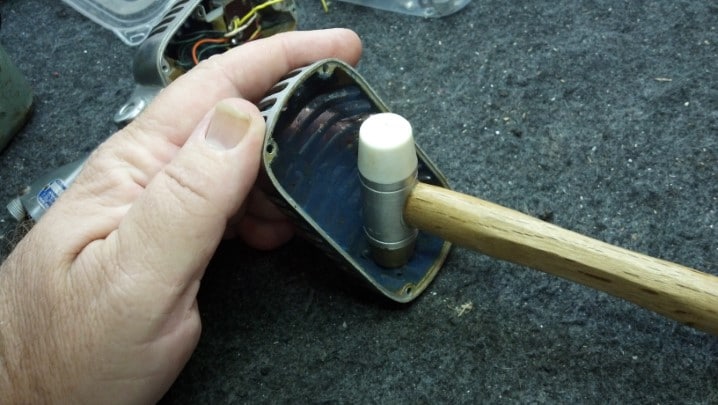
A dent in the body of the microphone needs to be removed. Yes, I’m using my luthier’s hammer to pound out the dent.


Can you see where the dent was?


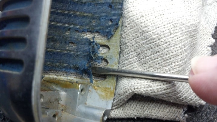
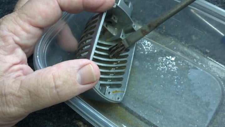
The old silk wind screen was glued inside the case of the microphone.


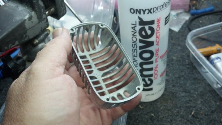
Acetone will dissolve the old glue. It will also dissolve silk, turning this cleanup step into a blue sticky ‘hot mess.’


But a little patience and perseverance yields a clean microphone case.


Warning – Skeleton Shot! I’ll betcha that you have never seen a microphone like this.


We found some sheer blue silk fabric for the wind screen. This brighter blue is not historically correct, as ‘Victoria Blue’ (Pantone 2756) was specified by the factory. However, this blue matches the Shure nameplate and badge.


This is a test.


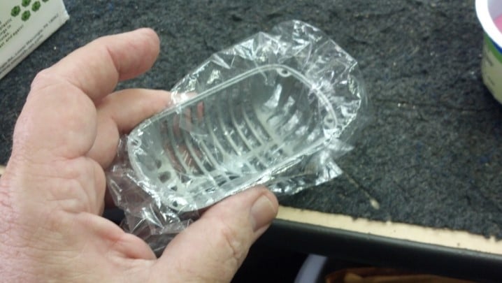
Fabric is glued to the top and bottom as well as sides of the front half of the microphone enclosure. We will now fabricate a soft pillow to allow the fabric to be ‘blocked’ into place as the glue dries in the front half of the microphone enclosure.


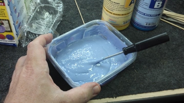
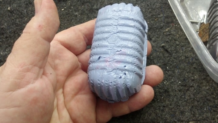
This soft pillow will be fabricated from Oomoo. Yes, the silicon mold-making resin will be just the thing.


Equal parts by volume are mixed.


The mix is poured into the front half of the microphone. A plastic sheet protects the microphone shell from the casting material. The Oomoo silicone mold material won’t hurt the microphone shell, but I don’t want to risk contaminating the microphone shell and possibly compromising the glue adhesion later.


And here is our pillow!


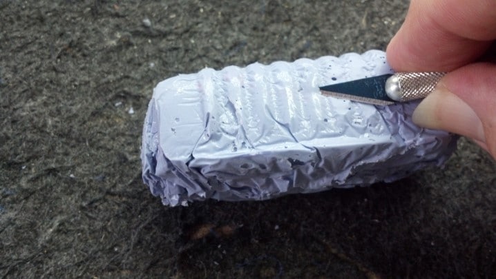
We don’t want the pillow to deform the fabric, so these high points are removed by hand with an Exacto knife.


Here is the finished pillow inside the microphone shell.


And here is the fabric, glued and blocked into the microphone shell.


Time to reassemble. The moving joint is reassembled and the cable from the base to the enclosure is reinstalled.


The spring around the cable is held in place with the set screw, as we discovered earlier. This is a nice view of the fabric in the back shell of the microphone. This piece is just a flat rectangular sheet stretched across the back, so it’s easy to glue in place by hand without a block.


The joint is back together. No lubrication is necessary as the graphite washers are doing their job.


A smooth, firm grip at the joint is established before installing the lock nut.


This is what the spring protecting the wires is supposed to look like.


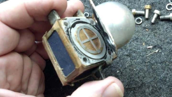
The microphone element works, but I couldn’t resist taking a look at the technology behind US Patent 2,237,298. The hemispherical shell on the back of the element helps establish the cardioid pickup pattern of the element.


I fabricated new foam vibration dampeners, which are installed in three places. The matching transformer assembly goes back where it belongs.


The microphone element is reinstalled where it belongs and wired in. This is now a working microphone. The covering on the microphone element is actually the same material used for vintage silk stockings a.k.a. nylons.


A set of four matching screws are fitted and finished to hold the two halves of the microphone enclosure together.


Pretty spiff!


Thanks for reading all the way to the end!

CONTACT – David Latchaw EE
281-636-8626

Marshall JCM900 Tune Up

This wonderful old Marshall JCM900 lives in a recording studio. It was due for a set of tubes and a million-mile checkup. Could the Unbrokenstring Crew refresh this head and resolve the tiny issues that had arisen over the years?


In simple terms, this head has two channels that share a common tone stack, effects loop, and reverb tank. The amount of reverb, as well as the gain and volume, are independently adjustable.


Name, rank, and serial number, please.


The effects loop is accessible from the back. This unit is recording-friendly, with outputs for ‘wet’ and ‘dry’ signals.


The Business End. This amp can be switched to 50 or 100 watt output power.


Two fuses are used in the high voltage plate supply for this amp, which is a nice touch and will add something to the story later. IEC mains power socket and a line fuse rounds out the rear panel.


These power tubes have pushed billions and billions of electrons around, and some of those electrons have interacted with the inert gas inside the glass envelope. Do you see the frowning face in the upper insulator? The brown scorch mark is his beard.


These great tubes have delivered a long service life and are now just about worn out.


Interestingly, Marshall delivered these heads with 5881 tubes, a military 6L6. Later 6L6GCs dissipate more power and take higher voltages. You can read Internet posts regarding the battles between Marshall in England and American importers; the latter changed the tubes on new amps to 6L6GCs because they believed the 5881s would not last through the warranty period.


And here we have the reverb tank.


A walk through the bottom of the unit shows us the output transformer. The red and black leads to to the reverb tank.


On the left is the preamp circuit board containing the input jack, tone controls, and signal switching. The tube sockets are discretely wired, and on the right is another circuit board handling the effects loop jacks.


More views of the preamp board on the left and the output jacks on the right. Tube sockets are in the middle.


At the lower right side of the output circuit board is the power supply power resistors, rectifiers, and fuses


The large blue items are the filter capacitors. These are in excellent condition and will not be replaced today.


The power transformer and power switches are mounted directly to the chassis.


This blue control sets the idling current (bias) for all four tubes. The current splits thru R28 and R29 to manage a pair of tubes each, part of the 50W/100W power control circuit.


The Unbrokenstring Crew are big fans of DeoxIt products. Here, we have sprayed a little D100 into the cap, and then soaked a pipe cleaner in the solution.


The pipe cleaner works well to clean and recondition each individual octal tube socket contact.


We will also wipe off the pins on the bottom of each tube.


So with the tubes installed and operating into an 8 ohm resistive load, we set the idle current for one pair of tubes. But the two sides don’t match.


Here, I’m using my good Fluke bench meter to confirm that one pair of tubes is idling at 50 milliamps, while the other pair is idling at about 41 milliamps or so. Both meters are in good agreement with the values measured, but I’ll stay with my good Fluke to investigate the situation.


Plate current causes heat to be dissipated in each tube. The V1 and V4 tubes are about 114 degrees C. while idling at about 41 milliamps.


The V2 and V3 pair are a little warmer. These tubes are idling at 50 milliamps. The temperature difference confirms the validity of the different idling currents… but why are they different? They share one transformer winding. We paid big money for matched tubes (which, when swapped around, make no difference…) More work!


Remember seeing separate fuses for plate current on the back of the amplifier? Checking voltage drops in the entire plate circuit, we see that this fuse drops about 0.2 volts across it more than the other fuse. Does that tiny voltage drop make any difference?


The fuse for the V1/V4 pair of tubes measures over half an ohm (meter zeroed for test lead resistance.)


This is the other fuse, for the V2/V3 pair plate circuit.


This fuse measures a tiny bit smaller resistance from end to end. Does this actually account for the higher current?


Sure enough, those voltage drops and differences in resistance accounts for about 10mA difference in plate current. New Fuses, Please!


While we’re at it, we will clean the fuse caps with DeoxIt, just as we did with the tube pins.


And the fuse holders will be similarly cleaned. (Hint – these pipe cleaners are perfect for cleaning other hardware besides your tobacco pipe.)


This line filter capacitor is scorched by a power resistor that was pushed up against it, perhaps a result of rough handling during shipping.


Components that are used on AC power require all sorts of safety certifications, which this part has.


I could probably leave this part in the amplifier, but film capacitors are cheap and if this were my amplifier, I would want it taken care of in a proper manner.


So here is the new line capacitor. The power resistor will be moved away from this guy when it is installed.


The filter capacitors in the bias circuit were also replaced, while troubleshooting the plate current imbalance.


Of course, replacing those parts requires access to the bottom of the circuit board.


While we have the circuit board up and out of the way, we can catch a glimpse of the discrete-wired tube sockets. This is a much better way to wire vacuum tube sockets, rather than solder them to a printed circuit board IMHO, because the tube sockets expand and contract much more than the circuit board material, whereas the discrete wire can just flex with the expansion and contraction.


This little bit of trimmed wire was stuck on the bottom of the circuit board. This will be no issue unless it comes loose, which it might do just as you are ready to go on stage and start the set.


Now this amp is running like a clock. The waveform represents the voltage across eight ohms driven with 110 watts, with a 440Hz sine wave injected into the input jack.


The chassis goes back into the case. I removed the power tubes for this step because I didn’t want to risk breaking anything in case I got stupid. The red and black cables to to the reverb tank.


Everything is checking out!


The sheet metal rear panel is much easier to align when the unit is face-down on the bench.


Zenith televisions were advertised with the slogan “The quality goes in before the name goes on!” After a four hour burn-in, the sticker is affixed on the output transformer side of the rear panel.

Thanks for reading all the way to the end!

CONTACT – David Latchaw EE

281-636-8626

Fender Princeton Reverb Amp is Snatched from the Jaws of Hurricane Harvey

Partially submerged in the flood waters of Hurricane Harvey, this combo amp was rescued when the waters receded.  Could the Unbrokenstring Crew turn this insurance claim into a working unit again?

 At first glance, this unit is in pretty good shape.  Fortunately, the flood waters around this unit were not salty, but fresh rain water.  The grille cloth was not badly stained, and much of the exterior grime was superficial.


Not much damage had occurred to the cabinet; some warpage was beginning to appear in the bottom baffle.  The interior was still wet.  This implied that, if the drying-out process could be controlled, no further damage to the cabinet would be sustained.


Can you see some rust on the screws?


This side has some mold.


The bottom Tolex has some mildew beginning to form.  Look at the rust beginning to form on hardware in the foreground.


The handle was beginning to rust.  This could be managed.


The handle and the Tolex is cleaned and reconditioned with this, which also gives us a clean lemon scent!


This is the top of the reverb tank.  Yes, beads of water, still on the exterior of the tank.


The previous owner had padded the top of the tank with gray foam, and the bottom with cardboard.  The cardboard was soaking wet.


Reverb tanks are inexpensive, so we will just order a new one.


The paper cone of the loudspeaker was intact.  This loudspeaker will be replaced by the new owner.


Moisture inside the amp chassis has swelled the turret board.


Water has reacted with the solder flux, creating a brown crust around all the solder joints.  The components still look pretty good, although they cannot be trusted now.


Corrosion on the tube socket contacts testifies to the presence of liquid water here.  Note also that the zinc plating on the once-shiny chassis is turning cloudy.  This tells us that the zinc is doing its job as a corrosion-inhibiting plating, sacrificing itself to protect the steel underneath.


The cabinet hardware is washed in Rust Biox to clear away the rust.  This chemical is available in Europe, but of course, The Unbrokenstring Crew is just cool enough to have this material here in the U.S.


The nickel plating has very little iron to rust;  This deposit is probably mud.


All the hardware is cleaned up.  The Tolex is cleaned and conditioned with the furniture polish.  The cabinet looks good as new!


A new tube chart is pasted inside the cabinet where the original one was located.


For the electronics, a hand-wired chassis from the estate of Darrell Shifflett of Texas Amplification is pressed into service.  The Unbrokenstring was truly fortunate to buy the remaining inventory of Texas Amplification.  This chassis was part of the inventory.  Look at those shiny new jacks!


The knobs are, of course correct.  This is a clone of a Fender Blackface Princeton Reverb, not built in California but rather in Houston, Texas.


Darrell was a master of the details.  Even the front panel is Correct for this unit.


As a testament to Darrell, let’s just take a look at his workmanship.


The wiring and component placement is meticulous.


If original components were available, such as the carbon composition resistors, he used them.  Modern flame-proof components are used where an improvement in reliability and safety without sacrificing sonic performance justified the upgrade.

Even the wire is period-correct, fabric-covered was used for the point-to-point wiring, just like the originals.


A bias check for EACH output tube is added to the rear panel.  Millivolts measured from red to black correspond to milliamps of plate current.


The jacks and controls are name-brand and not the cheap stuff.


But just look at that fresh brass sheet used for the ground plane under the controls.  The original brass probably didn’t look this good in Fender units when they were new!


The underside of this amp is just a voyage on the Good Ship Eye Candy!


The electronic tremolo circuit is duplicated on this turret board.  Not sure why this turret board is warped, but it is electrically 100%.


Speaking of turret boards, just look at the meticulous care used to mount each component and route the leads.  Even the bias potentiometer is nicely placed.


Comparing this layout against the original Fender drawings is just breath-taking.


I’m really jazzed about how the fabric-covered wire is carefully routed around the tube sockets.


We needed a new rectifier tube for this amp.


Darrell used Mercury Magnetics for all the transformers on this chassis…  the best you can get!


With the power on, all the voltages are correct.


The new reverb tank arrived today.


The bag protecting the reverb tank is dry and ready to be used again.


These straps hold the reverb tank bag in place in the bottom of the amplifier.


The ON/OFF switch works as it should.  Since the AC cord is a modern three-wire unit, the original ‘GROUND’ switch is wired as a STANDBY/ON switch.


This unit is ready to go back to the new owner, who will install the new loudspeaker.  Pretty nice unit for having been under water!

Thanks for reading all the way to the end!

CONTACT – David Latchaw EE
281-636-8626

A Journey To Planet Unobtanium – Yamaha 50-112 Combo Guitar Amp

A secret weapon of many an acoustic and jazz artist, this mid-seventies line of Yamaha solid state amps were well-regarded among those few who knew about them. This like-new specimen had been suffering from a strange ailment, then went mute. Could the Unbrokenstring Crew revive this unit?

On the exterior, this amp was in very good shape considering that it had been built forty years ago!


Starting our tour, the power switch combines the ON/OFF function with the AC polarity reversal switch seen on many tube amps of the same period.


The high and low level input jacks are typical for the era.


The tone stack includes a ‘bright’ function, a precursor of the ‘presence’ control seen on amplifiers today.


The presence of the reverb function demonstrates that this is an early unit.  Many of the later ones did not have a reverb tank at all.  The distortion function is an attempt to add ‘fuzz’ and is nothing like the metal/shred distortion heard today.


A few attempts had been made over the years to clean the controls.  Unfortunately, the lube spread onto the front panel around the controls.  Yuck!


The open cabinet is clean and functional.


We have the usual name-rank-serial number information here.


We have two unmarked jacks.  What in the world?  But we see foot switch jacks which are not out of the ordinary.


Both the AC power into the unit and the DC power to the final amplifier block are externally fused.


And, we have a QC sticker!


Removing one of the rear baffles reveals the solid state amp and gives us access to the chassis.


Obviously the original loudspeaker, the response graph demonstrates the heritage of this unit to the high fidelity world that Yamaha dominated in the 1970s.


This ground lead connected the chassis of the amplifier to the frame of the loudspeaker.


With the chassis out of the cabinet, we see a reverb tank in the foreground, a power transformer to the right, big capacitors in the center, and a mono-block amplifier to the left rear.


This strain relief for the AC power cord is really over-the-top!


The black, finned heat sink is the foundation upon which the power amplifier is built.


This large electrolytic filters the DC power for the amplifier, which is nominally 80vdc.


This electrolytic capacitor is in series between the amplifier output and the loudspeaker.  This amplifier’s circuit topography shifts the DC operating point of the amplifier to one-half of the DC power supply voltage, effectively forming a class AB amplifier using a single power supply.  This capacitor passes the audio current to the loudspeaker while protecting the loudspeaker from any DC current.


Underneath the chassis we find this fused, low-voltage power supply which supplies floating DC voltages for the circuitry.


Remember those two unmarked jacks on the rear panel?  Someone added them so that a quarter inch cable can be connected to another quarter inch cable.  Yes, this is a home-made 1/4″ mono to 1/4″ mono jack adapter/coupler.


Here is the bottom side of the two large electrolytic capacitors we saw up top.


More fuses and bypass capacitors are visible here, in vinyl tubing, to shroud the terminals from touching something they shouldn’t.


The ON/OFF/ON switch is seen to the right and the Power ON indicator lamp, with limiting resistor, are seen here.


Look at the thick steel shield that keeps any signals running around the inside of the amplifier away from the input jacks!


While we’re here, let’s service the unit.  Jacks are cleaned with De-Ox-It.


This circuit board handles all the signals surrounding the front-panel potentiometers.


These controls will be properly cleaned and re-lubricated.  And we can clean that nasty front panel while we’re here!


After removing two large bolts, the power amp assembly lifts off.


The six pin connector handles power in, signal in, and amplified signal out duties.


Inside this assembly, we see all the components for a transistor-based solid state power amplifier.


A pair of these transistors handle the power amp duties.  The screen separates everything from the collector of the transistors, which are at +80vdc potential.


This screw under the little bump in the sheet metal holds a temperature-compensating diode array in close contact with the heat sink.  This diode array provides temperature compensation for the transistorized amplifier.


Note that this module is stamped 50W/8 ohms.  The Japanese think of everything!


With the cover removed, we can see the inner details.


These low-level driver transistors are pure unobtanium, which means that if they are bad, there is no modern direct replacement.


Fortunately, all of those low-level driver transistors appear to be OK.  The curve tracer indicates that this is a PNP device.


This is another bit of pure unobtanium.  Three silicon diodes with special forward voltage characteristics over temperature are housed in this component.


This diode array appears to be functional for now.  These are HIGHLY SOUGHT AFTER by techs who rebuild those 1970’s era Kenwood and Pioneer stereo receivers.


Every component will be checked, including the power transistors.  Replacements are available for these, if we need them.


Almost every component will be removed from the circuit board and verified against the schematic and the markings on the device.


This capacitor was more than 30% low in capacitance, and will be replaced.  (No, the leads are not touching.)


With the power amp assembly back together, we can perform some initial setup of voltages and levels.


One of those two big power transistors with the copper-colored tabs is intermittent.  Can we find a matched complimentary pair to replace them both?


Yes, after some research, an adequate replacement was ordered.  Whew!


Here they are, those black boxy devices in the center of the picture.  I marked the collector pin locations with a C and the base pin locations with a B on the circuit board so I could get the new parts in the right place.


OK, now we’re cooking.  The center yellow trace is a signal called C.VOLT on the schematic, and represents the voltage value of the midpoint of the DC power supply.


Over a few hours, the value of C.VOLT changed, creating bad distortion.  Look closely at the green capacitor at the top of the picture.  Can you see something ‘wet’ on the circuit board under it?


That ‘wet’ looking stuff is similar to contact cement.  The Japanese used this stuff extensively in the 1970s to secure electronic components so that they did not come loose from the circuit boards when shipped to the United States and elsewhere.  Over time, this ‘stuff’ becomes conductive, which will upset circuit operation.  Many a Japanese-built bit of electronics, including televisions and Ham radios, were taken out of operation by this stuff.


The site where the green capacitor goes has been cleaned.  This needs to be repeated for any ‘stuff’ remaining in this unit.


Here is the C.VOLT test point.  The crusty brown stuff is solder flux, which will also be removed.

I uploaded a video of the working amplifier to YouTube, which then blocked the video and hit me with a take-down notice about a minute after I uploaded it.  The audio content of the video was copyrighted, and I was caught.  Don’t you just love YouTube/Google/Facebook?

Thanks for reading all the way to the end!

CONTACT – David Latchaw EE
281-636-8626

Phonic 1500 Rack Mount Stereo Amp Repair and Update

Billy was running this amp as part of his PA for years until one channel quit.  Could the Unbrokenstring Crew bring this inexpensive amplifier chassis back from the e-waste pile?
To some folks, Phonic and Professional do not belong in the same sentence.  But this unit has been working very well behind the scenes, for more years than many of its Brand Name Brethren have been working.


Simple controls on the front.  Cranked to eleven, of course.


It doesn’t get much simpler than this.


Billy asked to have an IEC power cord installed on this when (not if) we fixed it.


The Neutrik power connectors are a nice touch, almost required at higher power levels.


Inputs are either balanced quarter-inch TRS or XLR connectors.  The usual set-and-forget controls are found here.


The power transformer seems adequately-sized for this power level.  AC-to-DC duties are performed to the lower right, and one audio channel is seen between the transformer and the aluminum heat sink.


With the unit turned around, the other audio channel is found here.


The front panel controls are here.  These potentiometers will get a million-mile cleaning and lubrication.


The dark charcoal-colored ribbon cable connects signals to the two audio channels.  The flat ribbon is Just The Thing here, because it does not block the path of cooling air into the unit.


The electrolytic capacitors are bulged, which is not unusual for a unit that has seen this many years and this much use.


These electrolytics will be replaced.


These rectifier blocks are wired in parallel.  Yeah, Baby!


I was kinda wondering where the line fuse was located.  It’s under this bundle of cables.  Yes, that says 30A at 115VAC.


Before the unit comes apart, I need to document where all these cables go.


These cables need to go back where they started.


Behind the colorful bundle in the foreground is the circuit board that connects the rear-panel output connectors.


I need to remove the larger circuit board to get to the solder-side of the PCB.  The dirty little ribbon cable comes off first.


These output cables come off next.


And now, we begin.  There are about thirty screws that hold the circuit boards in place.


These little screws are everywhere.  Like that’s a bad thing…


More screws.


The heat sink is split into two sections, one for each channel.  They need to come loose from the chassis as well.


This aluminum block bridges the tops of the heat sinks to add strength and rigidity to this unit.  Nice!


OK, the main board is out of the chassis.


Interestingly, some other version of this amplifier uses more electrolytic capacitors.  In this version, the pads are jumpered.


Turning the board over, the solder joints to be cleared are ‘marked’ with some rosin solder flux so I can find them if I look away to grab the soldering iron and braid.  Yes, I’ve unsoldered the wrong solder joints in the past.


The old caps at the top of the picture are out and the holes in the PCB are cleared.


Meanwhile, back at the ranch, we will remove the captive line cord and add the IEC connector here.


This cord has 14AWG conductors in it.  A matching large molded IEC power cord will be supplied with this unit when it is returned to the customer.


Here is our new IEC male socket.  Some of these come with flange ears, but spacing on the rear panel is too tight to allow the use of one of those.  This one snaps into place.


This looks a little rough, but this is the approximate outline of the rectangular cutout for the new IEC connector.


While we are hatchet-ing on the rear panel, these magnets will catch any chips or bits of steel removed from the hole.


Here is the outside view of the first trial fit.


And this is what it looks like on the inside.  This IEC socket snaps into the hole, so the hole size needs to be right.


Here is the new IEC socket wired into place.


And this is the closeup of the finished installation.  That silver thing next to the CE mark is a ground point.  I temporarily removed the thumb screw while grinding on the chassis.  It goes back on the unit next.


Now it’s time to reassemble.  Screws, anyone?


Glad I took all those pictures of where these wires went!


The unit is now reassembled.


Here, the terminal block outputs are tested at 250 watts.  So far, so good!


The Neutrik connectors are tested next at 750 watts per channel.  All is well!


Thanks for reading all the way to the end!

CONTACT – David Latchaw EE
281-636-8626

MIJ Fender Precision Bass Gets a New Nut and Setup

Lisa’s marvelous Fender P-Bass needed attention.  Some of the open notes were dead, and the electronics needed some attention.  Could the Unbrokenstring Crew sort it all out?
I just love the pale yellow finish.  Except for a string, everything is here.


Yes, it really is Made In Japan.  Back in the day, ‘made in Japan’ was another word for cheap imported junk.  Nowadays, this is some of the better stuff, particularly in guitars.


Name, rank, and serial number, please!


An electrical test shows that we have no output.


A quick look under the hood does not reveal an immediate problem.  Hmmm…


Oh, this is it.  The ground point for the whole unit is this potentiometer body.  However, the ground wire to the output lead does not connect to the potentiometer body anywhere.


With that fixed, the remaining ground wires are cleaned up a bit.


The bridge ground wire made an intermittent connection to the bridge.  We need to remove the green corrosion.


OK, the electronics are now all up to snuff, and actually look pretty nice.


While we’re here, we’ll tighten the output jack and potentiometers a bit.


The knobs go on now.


Final test is performed with a signal generator and another bass pickup.  The signal generator excites the windings in a bass pickup from an Aria Pro II bass, which will be featured in a future blog post.  The test pickup is brought near the instrument’s pickups, and the magnetic field carrying a test tone is coupled into the instrument’s electronics.


The dead open notes are traced to a cracked nut.  Here, we’re cutting the finish around the old nut so that it can be removed cleanly.  The Exacto knife gets a new blade for this operation.


The old nut comes out in two pieces.  The crack expanded until the nut broke in two.  That’s why we’re replacing it.


Here is the new nut that the customer wanted installed.  Good stuff!


Oops.  Houston, we have a problem  This new nut does not fit the neck.


The new nut is just a tiny bit smaller than what is required for this neck.  What gives?


We can clearly see the difference in the sizes between the old nut and the new one.  This neck is the width of a five string bass, but it was delivered as a four string bass from the factory.  So, we will make a custom nut for this instrument.


A Tusq blank is radiused to match the radius of the fretboard.  I’m using an Exacto knife as a scraper.


The Tusq blank is cut to rough length with a fine saw.


It doesn’t take long to slice through the Tusq material with this blade.


This is a saw blade set that I use for sawing fret slots and general fine work on wood.


The blank is now shaped on the disk sander.  A piece of birch plywood serves as a raised table that can be placed very close to the abrasive surface of the disk, necessary when shaping small parts.


The blank is now pretty close to the rough shape we need.


The first trial fit shows that we haven’t cut it too small, yet.


This is a little better.  The ends are flush and smooth with the edges of the fret board.


In AutoCAD, a drawing is created showing the cross sections of the four strings and the width of the fret board in actual size.  The distance between the edge of the outside strings and the edge of fret board, established by factory specs, is drawn, and the position of the outside strings fixed.  We then subtract the diameters of the four strings from the width remaining.  This result represents the space between strings, which shall be three equal spaces.  This establishes the center lines of the inner strings.  The spaces between the strings are the same, not the center-to-center distance.


But, to cut the string slots, we need to know where the edge of the fret board is, and where the center lines of the strings fall.  These solid lines represent that information.


The lines which represent the centers of each string are transferred to the nut.


A shallow file cut is made at each string center.  Here, we are checking these cuts against the template.


These shallow cuts represent the eventual center of each string.


These cuts were made with a triangular mill file.  Nothing special, but accurate enough.


Here, we’re polishing up the sides and faces of the nut, in preparation for gluing the new nut in place on the neck.


The nut depth is established by the fret height plus a constant which is established by Fender (and can be adjusted a bit by a good luthier, like me, for best play-ability.)  This is the Secret Sauce of making an instrument a great instrument.


The slot depth is now established by this stack of feeler gauge shims.  They are held in place with rubber bands wrapped around the back of the neck.  I’ve taped off the head stock so that I don’t scratch it up with the end of a file.


When the file touches the stack of feeler gauges, continuity will be detected by this multimeter, and it will beep.  This is another check of slot depth, besides my eyeballs.


Here, the slots are cut.  With a little cleanup and polish, this will be a good nut!


The nut is all done and polished.  Looks good!


The action on this instrument at the twelfth fret is pretty high…


We have a metal neck shim between the neck and body, made from a piece of the machinist’s feeler gauge of the proper thickness to reestablish proper neck geometry.  The metal shim is the hardest practical material for this purpose, with an accurate thickness, and better mechanical stability and hardness for greatest vibration transfer between the neck and body than a guitar pick or a piece of business card.  This results in the best tone.  And a set of feeler gauges are less than five bucks.


A quick adjustment gives us just the right amount of neck relief.  (Sharp-eyed readers will spot the fact that the strings are off in this picture.  This is the only pic I took of the truss rod adjustment, setting the neck flat while the neck shim was being sized.  Who cares if my pics are out of chronological order?)


To set intonation, we needed to work on the bridge.  Here is the underside of the bridge, probably not seen for decades.


The intonation screws were dinged.  Here, we are chasing the threads with a die to clean them up.  Yes, they are English/Imperial threads, not metric.


The bridge is tightened down and ready to go!


The moment we’ve all been waiting for!  Add strings, tune up, intonate, and play!

Thanks for reading all the way to the end!

CONTACT – David Latchaw EE
281-636-8626