
A lot of capable technology lives in this device. However, if the musician can’t select a configuration because the big rotary selector knob broke off, then it’s e-waste. Can the Unbrokenstring Crew bring this pedal back from the dumpster?
 Pedals live on the floor, and there is plenty of dust to attest to to the fact that this unit has been working hard exactly where it was born to be. No harm in cleaning and detailing this unit before we’re through!
 The main issue here is the broken rotary encoder. We have the knob, but not the shaft.
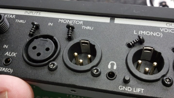
 Time for a quick tour before we begin. This pedal serves both vocal and instrument duties. Flexible monitoring options are available, as well as 3.5mm stereo headphones out and line-in capability.
 Separate paths are maintained through the unit for vocal and instrument signals. Stereo effects are available.
 Midi, USB in and out, and a power switch complete the rear panel. That black rectangle above the USB ports is a cleat to tie off the power cord, to make it a little more difficult to pull the barrel plug out of the power jack.
 It takes a lot to get into this box. Let’s start at the bottom.
 The bottom lid is off. So far, so good.
 The footswitches are VERY old school, rugged American made switches, proven reliable since the middle of the century.
 Let’s remove the sides next. This bracket on the side panel supports the bottom circuit board.
 These are the external screws on the sides.
 These are Torx-head cap screws, giving the device a cachet of ‘tamper-proof-ness’ unless you have the right tools.
 Next, the rear panel comes off. More Torx screws.
 Under the side plates, metal plates support the unit to make a very strong metal box surrounding everything.
 At last, we can get to the next layer. The unit is still upside down.
 I’m documenting where cables go. This is a front-panel indicator assembly.
 More cable documentation. See the Ruffles potato chip?
 Most of these cables will be marked with a Magic Marker to identify them for reassembly.
 Next, the front panel is removed. These knobs pull off.
 There are no lock nuts under these controls. Interesting…
 We have a few more screws to keep track of. Many of these are a certain length, and shall be returned to the right place.
 The LCD is tilted back to gain access to a few more Torx cap screws. Our final objective is in sight!
 The broken rotary encoder is on the same circuit board as the LCD. To minimize stress on the circuit board, the old rotary switch is cut away, leaving the individual leads in place. These individual leads are much easier to de-solder.
![]() The holes where the new encoder goes are cleaned and ready to go.
The holes where the new encoder goes are cleaned and ready to go.
 This rotary encoder is a special order part. Not just any component will fit.
 This is a workmanship check of the solder-side of the rotary encoder.
 And here is the component side. Again, not just any part will work here.
 We can take a break and do the clean-up prior to reassembly. Compare this with the first picture. Yes, the LCD window has been cleaned and polished.
 Reassembly is the reverse of assembly (wow, that’s profound.) The correct fasteners must be reinstalled at each step.
 Everything is back where it belongs. Remember the Ruffles potato chip? That is actually a dab of adhesive that secures the flat ribbon cable. A dab of silicone will be added in a moment to secure the ribbon cable again to the same spot.
 Looking good! Everything initialized. The factory reset procedure is complete.
 Somehow, I thought that this was an appropriate preset screen to display. I think we’re done!
Here is a video showing how the rotary encoder works to change presets and configure the unit into different operating modes.
Support this band! – Fake Believe
Thanks for reading all the way to the end!
CONTACT – David Latchaw EE
281-636-8626