DigiTech Screamin’ Blues Pedal Refurb

Jim purchased this used pedal from a national retailer.  It worked at the store but not at home.  He took it back and the national retailer wanted him to buy a new pedal.  Could the Unbrokenstring Crew help?  Check It Out!

This pedal is absolutely mint;  No sign that it had ever been used.  We hooked it up and it was non-functional on internal battery power, but worked perfectly using an external pedal power source.  Well at least the electronics work!

Let’s put a new battery in it.  Oops, when we pulled the battery, this corrosion was all we found.

Everything is made in China, but could we at least use a name-brand battery that wasn’t dented, Mr. National Retailer?

We loosened up the nuts on the jacks and removed the case screws.  Fortunately, the electrolyte did not leak very far.

Here is a view of the top of the circuit board.  We can easily replace the battery clip leads and get this back on the air!

While we’re here, let’s indulge in a little Tech Porn.  The printed circuit assembly is a nice mix of modern surface mount parts and quality film capacitors, with some small electrolytic caps where it makes sense to use them.

The circuit side of the board is uninteresting unless you are into this sort of thing.  Those are some tiny vias!

The red and black wires on the left are the battery leads, which will be de-soldered.  The long potentiometer shafts reach all the way through the top of the unit and out where the user can reach the knobs.

Another view of the top-side printed circuit board assembly.  These battery leads are coming off now.

The battery leads are unsoldered.  This unit was built with high temperature lead-free solder, but poses no problems for rework such as we are doing here.

Meet the new battery clip.  The case of the pedal has been clam-shelled around the circuit board assembly and we’re installing the screws and connector hardware.

The nuts on the jacks are tightened by hand with a socket.  A layer of felt glued to the socket prevents damage to the finish of the pedal.

The knobs press on, no setscrews.

The foot pedal lid was reinstalled and the unit tested fine with the battery.  Moral of the story: Buy name-brand batteries and don’t leave them in the unit and forget about them!


Thanks for reading all the way to the end!

CONTACT: David Latchaw  EE

281-636-8626

Shure 555H Microphone Rebuild

Another well-worn road warrior from Dr. Shoen is on the bench for service.  The foam is shot.  The on/off switch is always in the ‘on’ position, regardless of what the switch says.  The Unbroken String Crew goes to work!

The slide switch is under this cover.  I’m using a rag on the desk top to keep the small parts from bouncing away.

When the switch is in the ‘off’ position, the signal line is shorted to ground.

Speaking of small parts bouncing, this sliding contact is supposed to be inside the switch.  What’s going on here?

Here is an internal view of the switch wiring cavity. The spring is a flexible conduit of sorts, protecting the wiring that goes up to the head of the microphone to the cartridge itself.  The yellow and black wires allow the user to switch off the microphone by grounding the audio signal.  Or that’s the way it’s supposed to work.

Had the other ‘pole’ of the switch been soldered, the switch would have appeared to work properly. Hmmm…

In any case, we need to de-solder the switch so that the internals (including that sliding contact in an earlier picture) could be reunited with the rest of the switch, and the wiring will be replaced as we found an intermittent connection due to a broken wire inside the insulation somewhere.

This is a good view of what happens with a double pole, double-throw switch.  The pair of sliders work in unison to control two different circuits (double pole) and operate in two possible configurations (double throw.)  The folded tent-like structure is a spring which holds the sliding surface against the physical wiring contacts, which are the six metallic squares seen in the part of the switch in the upper right part of the picture.

Putting it back together, we have a better view of how the sliders relate to the physical wiring contacts.

Squeezing the switch together like this compresses those tent-shaped springs.  This pre-loads the contacts together to establish good contact.

Quickly, before I lose my grip, I gotta crimp those tabs back down so that the switch is held together again.

All four tabs are down flat, so this switch will be good for another million miles.

Let’s take the rest of the mic body apart now, to do something about the deteriorated foam.

A fine wire brush on the Dremel tool makes short work of the remaining foam. The dark lines are the old adhesive.

The front half of the shell cleaned up pretty well.  I’ll set this aside for now.

Here is the microphone capsule in its holder.  This all comes out to repair a broken wire as well as replace the windscreen foam on the capsule and the back half of the microphone shell.

The actual microphone capsule is held in the plastic holder with this big aluminum ring.

One of these wires were broken inside the insulation, so the wires will be replaced.  This pic was mainly to document which color went to which terminal.  I believe that the red magic marker indicates the ‘hot’ audio terminal.

The wire wheel made short work of the remaining foam in the back section of the microphone case.

For decades, technicians have used “Blue Shower” to remove corrosion and dirt from sensitive electronics.  Nowadays, more modern products have come to the market, and this is one. But I still keep my last can of Blue Shower in the chemical cabinet for those times when I need the Good Stuff!

Rather than spray the whole microphone with cleaner, I sprayed some into the cap, then will brush it onto the places that I want to clean up.

And this is my brush.  This brand of cleaner is a pale orange.

This is a good shot of the cleaner doing its work.  Compare the uncleaned pin in the background with the pins in the foreground that have already been cleaned.  And look at the junk on the swab!

The microphone is getting a new wire harness.  This is the back side of the connector in the previous picture.

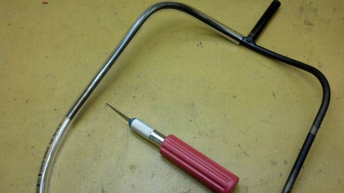
To pull the wire harness and the protective spring through the rear shell, I’m using this old guitar B string.

This is a glimpse of the B string and the wire harness moving up through the body of the microphone.

The wires to the microphone capsule are blue, yellow, and black.  The switch is wired with yellow and black.

The microphone connector is now fastened into its pocket in the bottom of the body.

Now that the microphone connector is secured, the internal spring can be tensioned and its end secured under the set screw shown here.

Our switch can be wired up and put back where it belongs.  This time, I’m using both sections of the switch.

The foam on the microphone capsule is completely gone.  A small round piece of foam will be glued here.

Not perfectly round, but who will know besides you and I?

This foam comes in large sheets.  Here, I’m fitting a small piece of the foam in the rear shell.

This is what it will look like from the outside.  Now we’re getting somewhere!

Trim the foam to fit.  No rocket science here!

The rear shell foam is ready to be cemented into the shell.

The same approach will be used to pre-fit the foam piece that will be cemented inside the front shell.

This aerosol can is what my mother-in-law would call a ‘Free Methodist’ spray can.  It sprays adhesive everywhere.  To keep the application of cement under control, I’ll repeat the applicator trick that I used to clean up the microphone connector, and use an applicator to put the adhesive right where I want it.

Here, I’m using a disposable paint touch-up brush to apply the cement to the inside of the front shell along the same lines used at the factory.

This is starting to look like a microphone again!  This is the front shell.

By controlling the application of the adhesive, I didn’t have to worry about removing a bunch of over-spray.

This is a rubber plug that serves as a strain relief at the point where the internal wiring enters the plastic shell holding the microphone capsule.

This is about the final resting place of the rubber plug.  Now we can trim the rest of the wiring to length and solder to the microphone capsule.

The wires are soldered and we’re re-assembling the plastic shell supporting the microphone.

The body of the microphone is almost complete.

Four more screws to reattach the front shell, and we’re done!  Dr. Shoen loves the aesthetics of this microphone, don’t you?

Thanks for reading all the way to the bottom.  This was another long post, and I hope you see the attention to detail that the Unbroken String Crew can apply to your repair or restoration project.

Contact Info :  David Latchaw EE

281-636-8626

Line6 M9 Multi-Effects Pedal Checkout

Steve really liked this pedal and gigged with it constantly.  However, one day, he found that he couldn’t control it through the stomp buttons.  The screen lit up, but nothing could be configured in the screen, and the pedal was useless.  The Unbrokenstring Crew rides to the rescue!

02 DisassemblyYogi Berra said “You can observe a lot just by watching.”  Sometimes, a little exploratory surgery will make the problem more apparent than going through the electronic menus.  We’re going in!

03 DisassemblyIt’s a little tricky to get the halves apart, but a little patience and good lighting lets you disassemble the unit.

04a Red PCBsIf you design your own circuit boards, as I do, you can order your circuit boards with any color solder masks.  I see that Line6 used red.  I’m good with that.  Although I use red solder masks with prototypes, and green for production.

04b Red PCBsThe top row of stomp box buttons are fastened to the large circuit board at the top, with the DSP engine right in the middle.  The lower circuit board handles the bottom four stomp box buttons.  What do we have here?

04c BeerNothing like a little spilled beer to brand this pedal as a gigging, mud/blood/beer-stained Texas Rock and Roll weapon.  But the beer is not the problem.

05 Cap1Nor is this the problem.  But it points us in the right direction.  Hot glue is commonly used in electronics, for encapsulation and adhesion.  Here, a blob of hot glue kept this cap down on the circuit board.  Or it should.

09 Hot Glue MagicHere’s another big capacitor held down with hot glue.  Any guesses yet why this pedal failed?

08 Hot Glue MagicI’m using the hot air rework soldering iron to soften the hot glue and stick down the big caps.

06 Loose07 Thats Better


Do you see what I just did?  The pedal was dropped, and the force of impact unseated this connector.  And it dislodged the big capacitors.  Now that the connector is reseated, everything works fine.  Easy Peasy!

10 ReassemblyThe unit is reassembled and checks out fine!  The firmware in this unit is update-able through the MIDI port, so if you need to update an older unit, you will need to connect this unit into the MIDI chain on your PC or laptop as there is no USB configuration capability.  But the factory reset can be done through the menu, and is well-documented on the Line6 Web site.

Thanks for reading all the way to the bottom!

Contact Info :

David Latchaw EE

281-636-8626


The Battery Leaked in this Electronic Tuner

I picked up a stack of these for ten bucks at a local music store.  They were all returned by customers who had problems with them.  Figuring a guitarist can’t have too many tuners, I sorted through them and got them all running.  Except this one:

The battery had leaked.  The ‘stuff’ that makes alkaline batteries work is (wait, wait, get ready for this…) alkaline in nature.  The caustic stuff, left on cadmium plated iron, was too much and the iron rusted.

Pretty nasty stuff.  Applying power directly to the circuit board, this tuner worked, so all I had to do was fabricate a new battery terminal.

This is a nickel-steel B string from an electric guitar.  It was too short to use anyway, but would be just fine as a springy, solder-able raw material to fabricate a new battery terminal.

With a little fiddling, I got it about the right shape and size.  Here, my handiwork is compared to the undamaged terminal at the other end of the battery stack.  My new terminal was shaped (crudely) as a cone-shaped spring, or close enough.

Here, we’re checking the newly-repurposed B string for a fit into the slot that will hold it when the batteries are installed.

The new battery terminal will be soldered to both sides of the circuit board here.

This is the solder joint on the other side of the board.

I think this crazy idea might actually work!

Tiny Phillips screws hold the circuit board against the LCD.  Connections to the LCD are made with Zebra strips.  What’s a Zebra strip?  Google it, if you’re interested.  And it has nothing to do with animals.

A fresh set of batteries are installed and the unit is checked.  WooHooo!

I had enough of these repaired that I gave them to other musicians, and I kept one in the guitar setup tool box as a spare.

This post just reinforces the old story about the electrical engineer who is the only person in town who will pull a five dollar transistor radio out of the trash and spend all day fixing it.  This project rates right up there with the transistor radio project, but at least it didn’t take all day!  I thought it was fun.

CONTACT INFORMATION – David Latchaw EE    281-636-8626

Teflon Coated Guitar Stand

Front

A few guitar brands, Gibson, for instance, uses nitrocellulose lacquer to finish their guitars. This finish may be easily marred by just touching other objects, particularly when the finish is less than a year old.  In this project, I wanted to explore alternatives to surgical tubing used on inexpensive guitar stands, with an eye towards protecting nitro finishes. NOTE – Special thanks to the local band “Jealous Creatures” who donated this stand to The Unbroken String Crew.

RawTubingThe old surgical tubing that originally protected the guitar from the metal parts of the guitar stand was already gone, so some quarter-inch vinyl tubing would be a good cushion over the bare metal. For most guitar finishes, you could just use this tubing and call it done, but I wanted a layer of something really inert in contact with the guitar.

CutHereHere, the vinyl tubing is cut to length. The plastic end caps would be reused in this project, and the vinyl was cut to length to accommodate them.

TopBracketThis is the support for the neck of the guitar, with the vinyl tubing.

TubingBottomHere, we’re covering the bottom support with the vinyl tubing.

GettingStartedThis is a roll of one-inch-wide Teflon plumbers tape, As you can see, I’ve begun covering the vinyl with the tape. There is no adhesive on the tape, only pure Teflon, so those black end caps will hold the beginning and ending ends of the tape in place when we’re done.

WrappingEach layer of tape overlaps half of the previous layer.

KeepWrappingCrossing over the half-way point, you can see that I just jumped across the bar in the center and continued covering the vinyl tubing with Teflon.


AtTheEnd

The other end of the Teflon tape is wrapped all the way to the end.

FirstCapThe little black end cap covers the loose end of Teflon.

BottomWrappedThe bottom support is finished.  The top support that goes around the neck of the guitar is covered in a similar manner.

BurnishTeflonNext to the black cap, you can see the overlap in the Teflon tape. To finish the job, I used my fingernail to smooth out the wraps of Teflon. The wraps disappear and the Teflon appears to be painted onto the stand. It’s a little harder to see, but the Teflon wraps near my fingers have been burnished and the wraps disappear.

FinishedStand
The finished product.

This project is not intended to be the last word on protecting nitro finishes, but rather is to encourage luthiers and guitar enthusiasts to think outside the box. There is a school of thought that damage to nitro finishes is caused solely by the mechanical pressure on the soft finish, and that this damage can be polished or buffed away. In other cases, some discoloration may occur when the guitar is stored next to leather straps or other sources of chemical impurities, and this damage cannot be repaired without refinishing.

Back
Who would risk damaging the finish on this 1968 Gibson SG Junior in Arctic White? Not this fat boy!