PreSonus StudioLive 18.0.2 Mixer Is Resurrected from the Dead

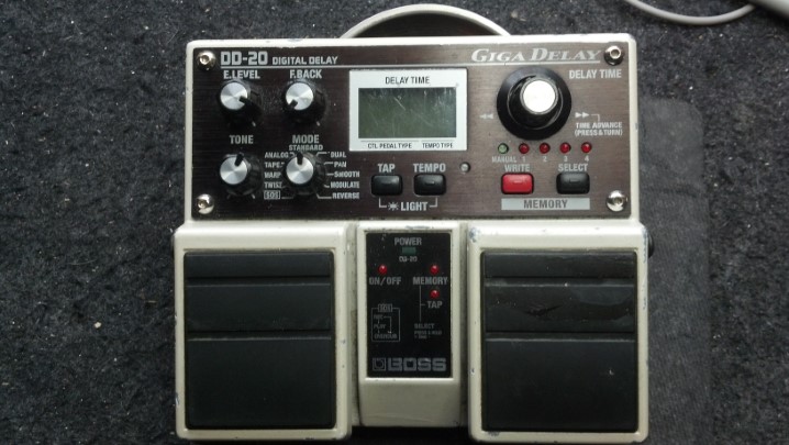
Richard relied on this unit for much of his sound, and when it went dark, he had to get it fixed or change his entire setup. Could the Unbrokenstring Crew bring it back to life and preserve Richard’s workflow?

.

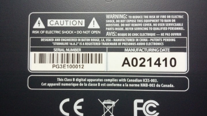
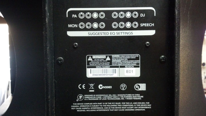
Our Cajun neighbors designed and engineered the mixer.

.

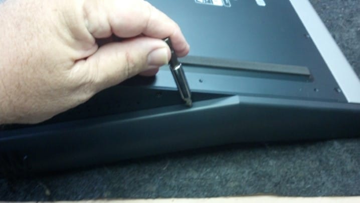
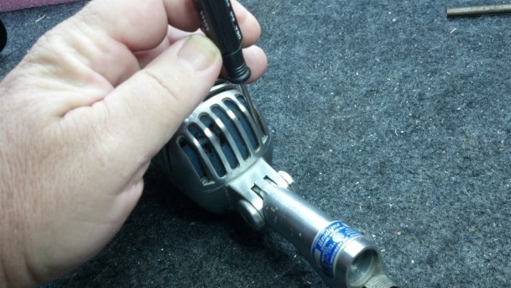
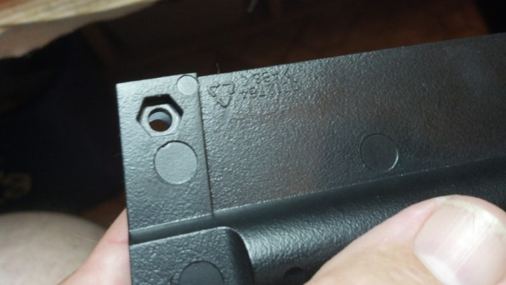
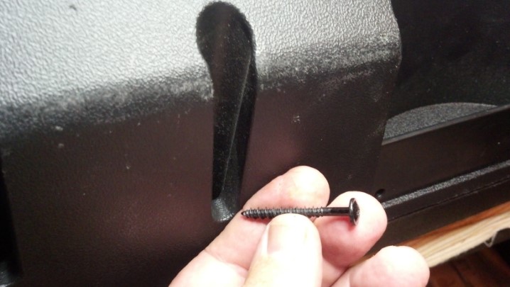
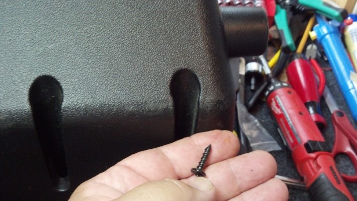
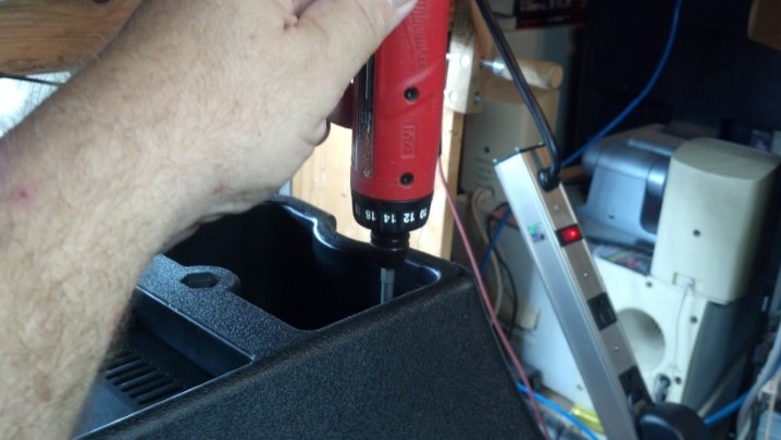
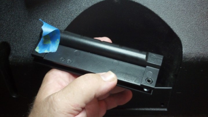
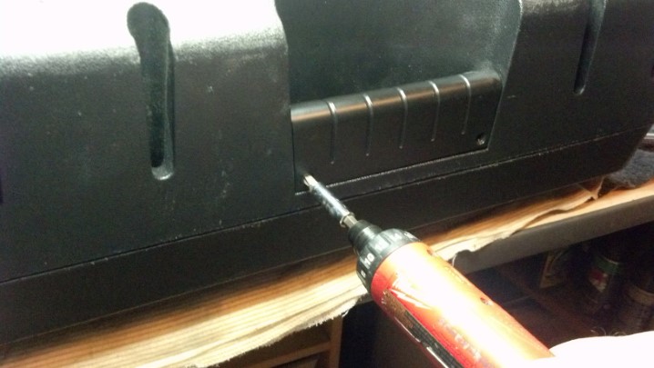
Two screws hold on the side trim pieces.

.

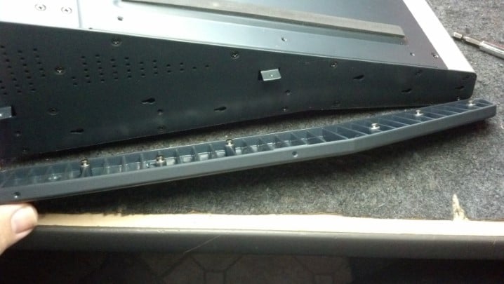
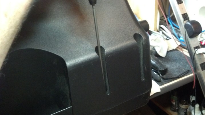
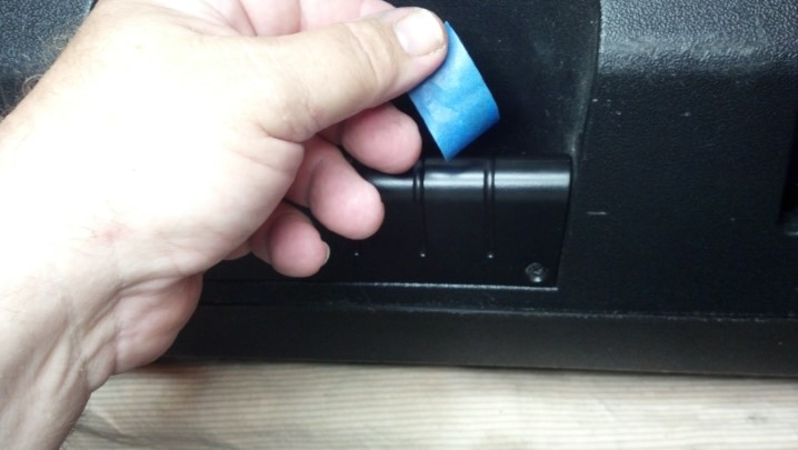
Once the screws are removed, the whole trim piece slides to one side and all these machined studs come out of the slotted holes. Nice.

.

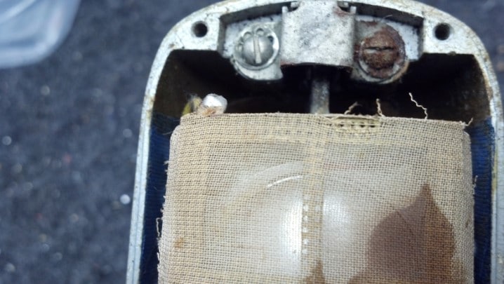
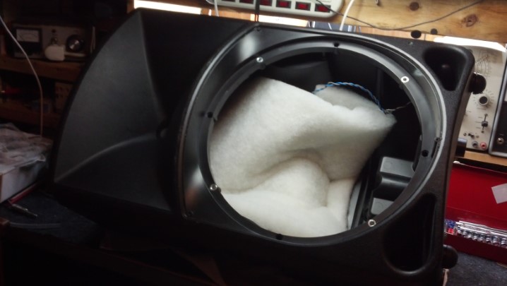
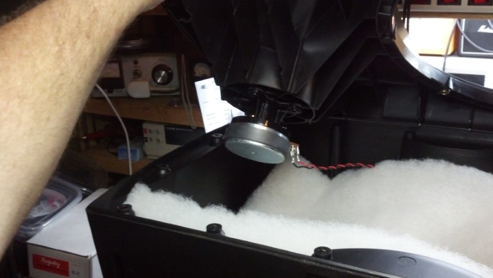
These side panels provide most of the mechanical strength of the finished assembly. Lots of little black screws hold them on. The red plastic tray on the right keeps them off the floor.

.

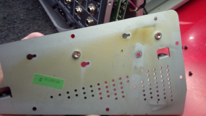
Inside the panels, we see tell-tale signs that the Magic Smoke has been released. Please understand that Magic Smoke is a very, very technical term.

.

Whenever the Magic Smoke is seen escaping from electronic components, they stop working. Therefore, all electronics must operate based on the principle of Magic Smoke. And you thought it was voltage and current…

.

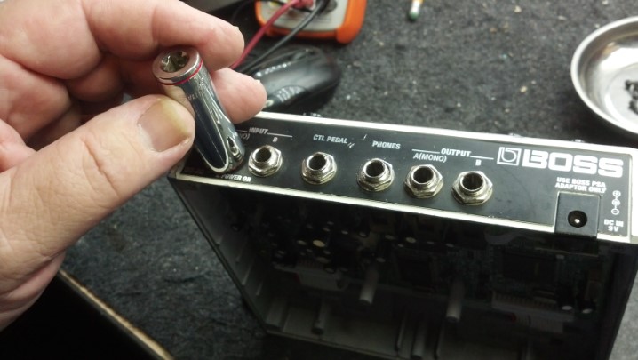
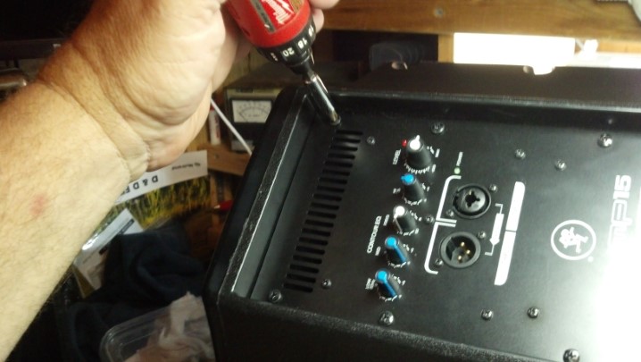
The fasteners used throughout the unit are tiny Torx machine screws.

.

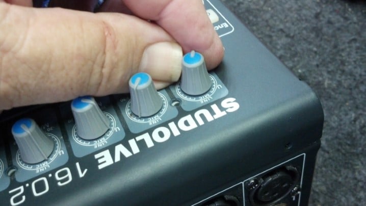
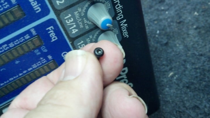
Sooner or later, all those knobs will need to be removed. For now, we will just remove the top row of knobs.

.

Now we can separate the rear of the unit from the front and back.

.

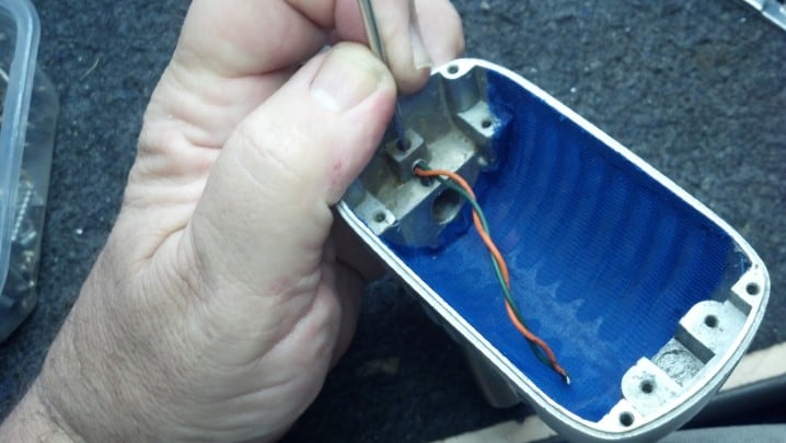
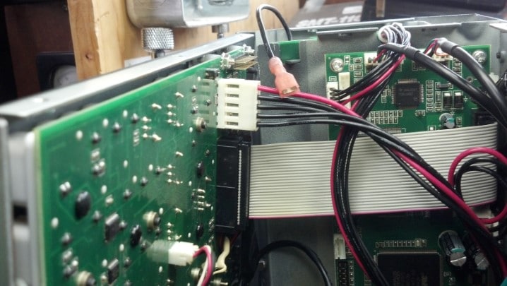
Power and data go thru these cables. I snapped a pic to be sure that they are oriented correctly when the unit is reassembled.

.

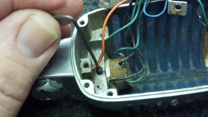
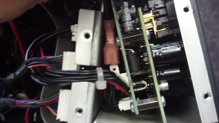
The brick red connector is a push-on terminal that connects the chassis grounds together. It must come off, but it’s in a recessed spot between circuit boards.

.

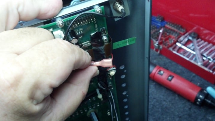
But the chopsticks came in handy and the ground terminal is free.

.

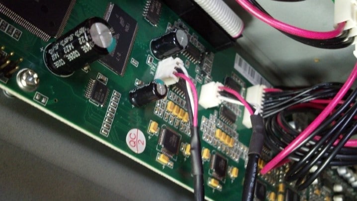
More pics to document where the cables go.

.

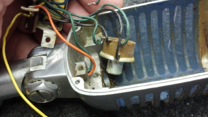
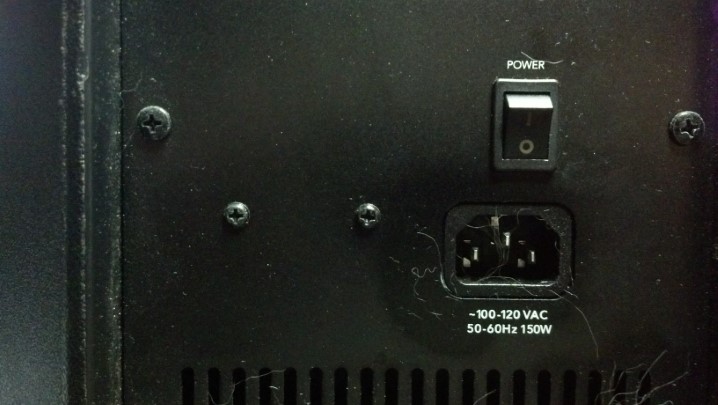
This is where the AC power is applied to the power supply assembly.

.

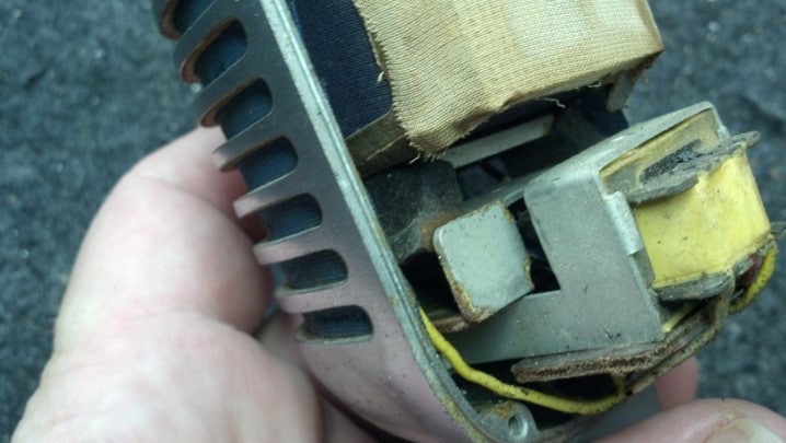
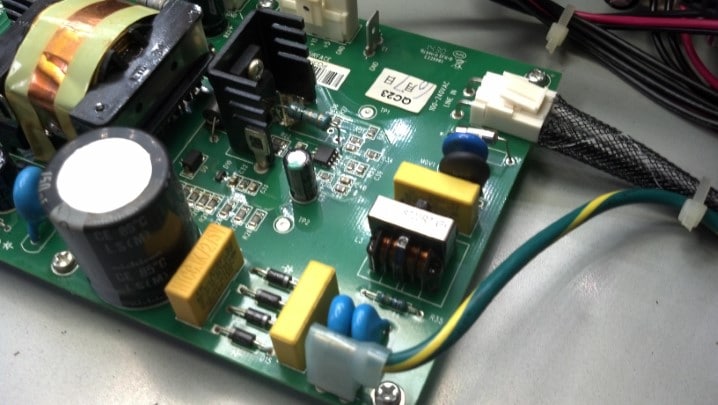
The safety ground is the green and yellow wire. AC hot and neutral are applied via the mesh-covered cable on the right. A fuse, surge suppressors, and a temperature-dependent resistor are seen here, along with AC-line-rated filter capacitors and a filter choke. BTW the fuse is fine.

.

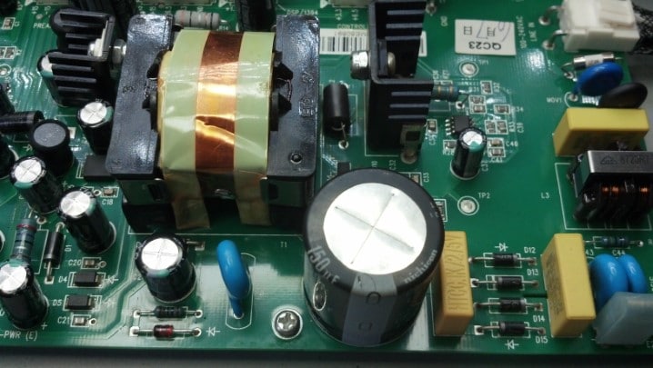
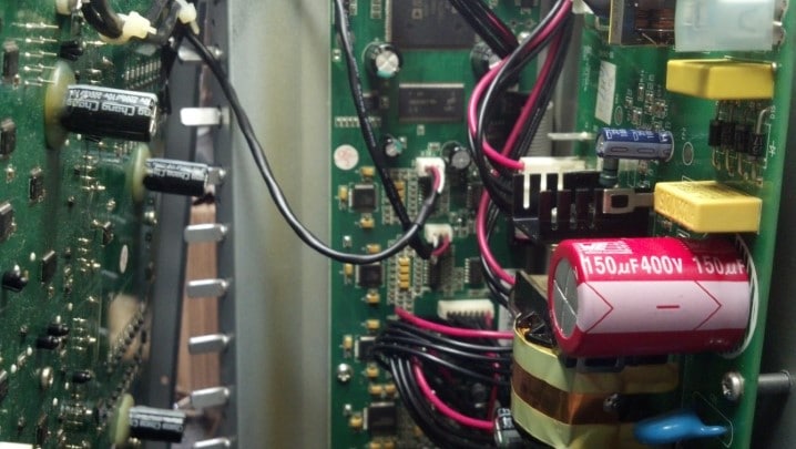
AC power is rectified and stored in the large capacitor in the foreground. The rectifier array is seen between the yellow blocks in the lower right hand side of the circuit board.

.

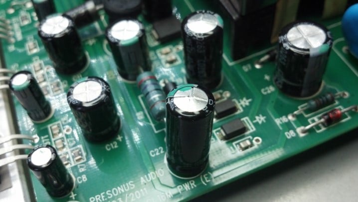
After years of service, the capacitors are swelling. Look at the top-facing end of the black cans seen in this picture.

.

When electrolytic capacitors swell, the chemicals inside are reaching end-of-life. The capacitor begins to dissipate more heat and energy storage in the capacitor itself become less efficient. And this cap is next to a heat sink, which likely is warmer than the surrounding areas on a good day.

.

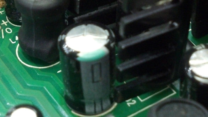
More swelling. These eventually pop and make a huge mess.

.

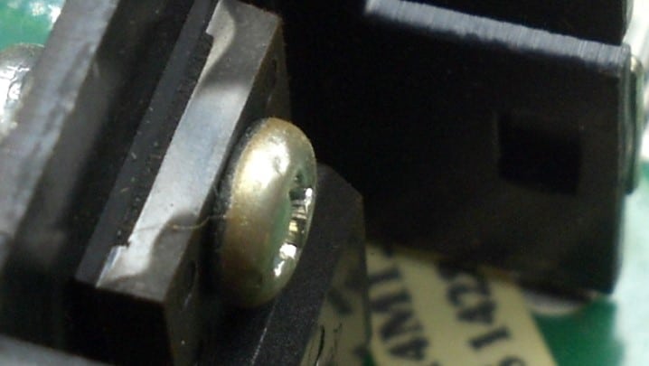
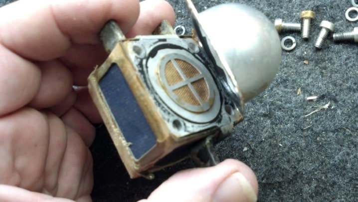
Looking at the reflection on the top of this device, we see signs that Magic Smoke escaped from this part.

.

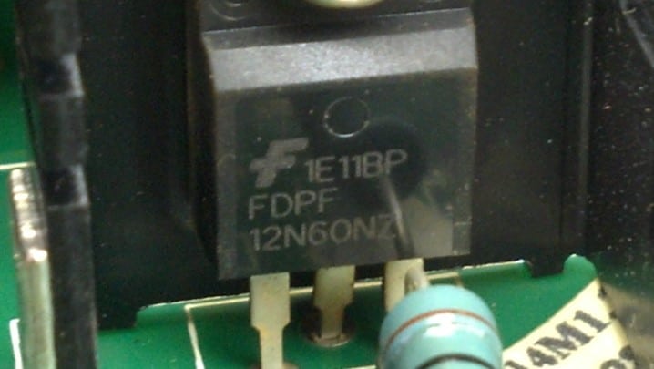
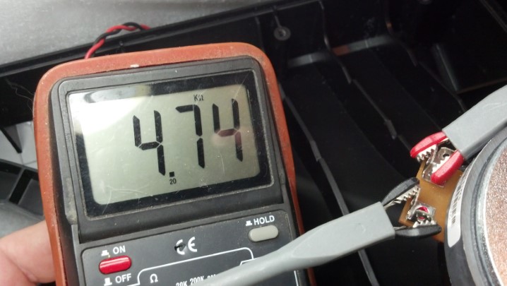
This part is a power field effect transistor (FET) and will be changed out. Electrically, each pin is shorted to the other.

.

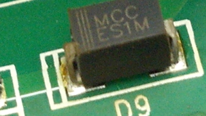
Magic Smoke has escaped from the end of this diode.

.

More magic smoke was seen in the vicinity of this part. These are cheap enough that it will be replaced.

.

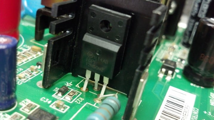
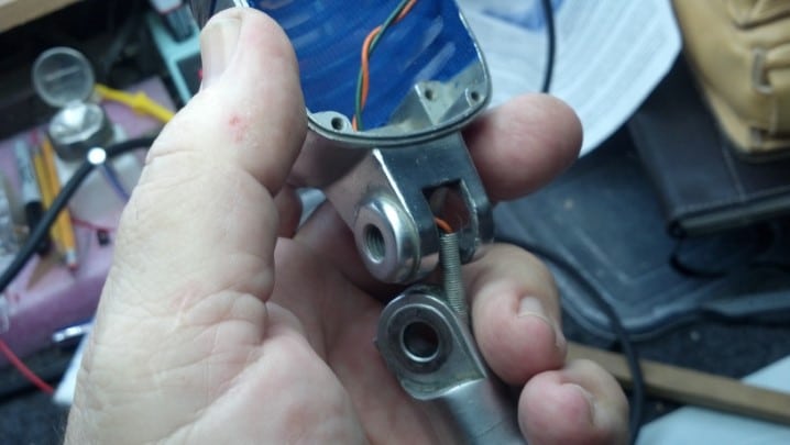
Here is the new power FET, ready to be bolted in place. Only after the FET is fastened in place will it be soldered to the circuit board, assuring us that the solder joints will not be under mechanical stress.

.

I tried to match components, but this big red gaudy storage capacitor was the only color available. Esthetics Fail. Sorry.

.

Every electrolytic capacitor in the power supply was changed. The suspected bad semiconductors have been replaced as well.

.

Fortunately, whoever did the circuit board design silkscreened the voltage values next to the pins where these voltages can be measured.

.

Armed with that information, we can test the power supply and verify that it is functional before connecting anything else that may be damaged if the power supply is not functional.

.

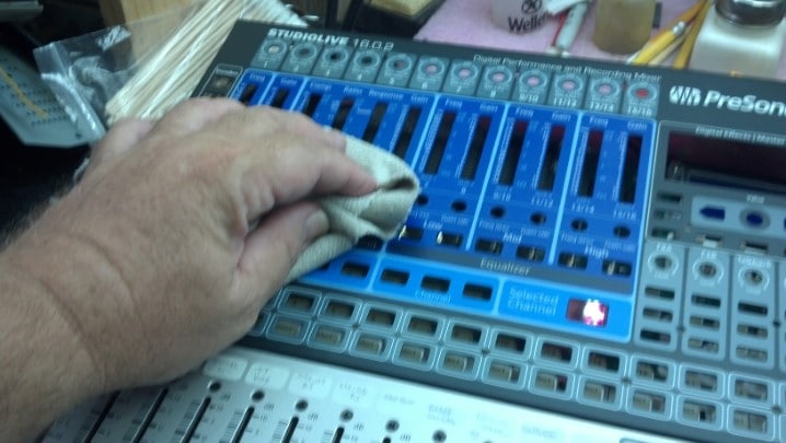
We are ON THE AIR! Everything works as it should. Except…

.

Can you see the cloudy area on the left edge of the LCD? That is not a reflection. That is more Magic Smoke. The LCD is fully functional, but this is just plain unacceptable.

.

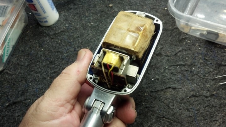
To gain access to the LCD, we need to disassemble the keyboard portion of the unit. And remove the rest of the knobs.

.

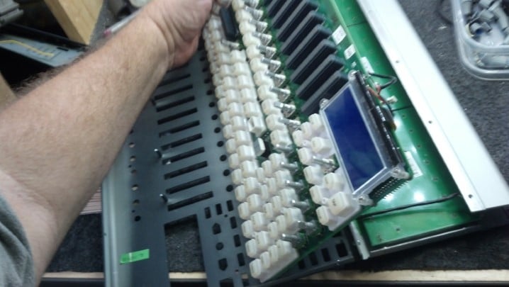
With more screws removed, we have access to the LCD assembly.

.

Opening the LCD allows for the inside of the lens to be cleaned and polished, removing the Magic Smoke.

.

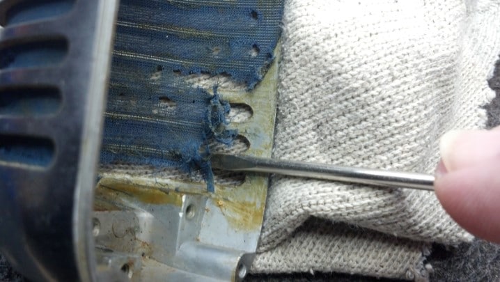
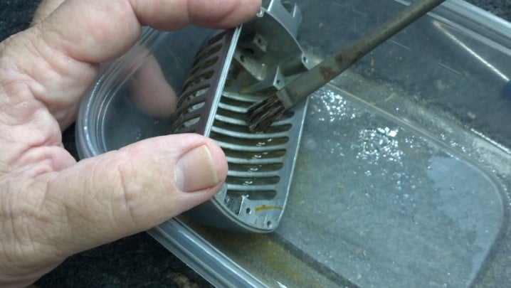
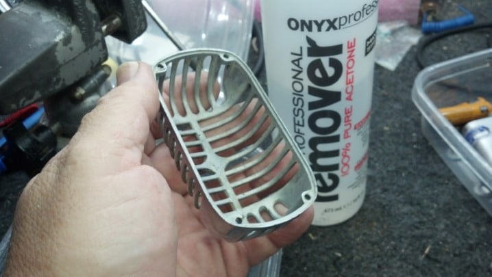
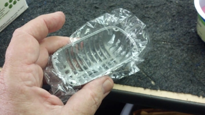
While the keyboard is apart, the sheet metal panel can receive a little TLC.

.

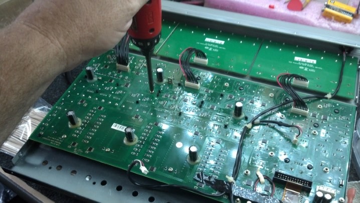
Aw, what the heck. While we’re here, let’s inspect the remaining circuit boards, looking for aging capacitors and signs of Magic Smoke.

.

An effects processor IC is seen here, along with many hybrid analog gain blocks. No schematic would help us through this maze. But everything here is in Tip Top Shape.

.

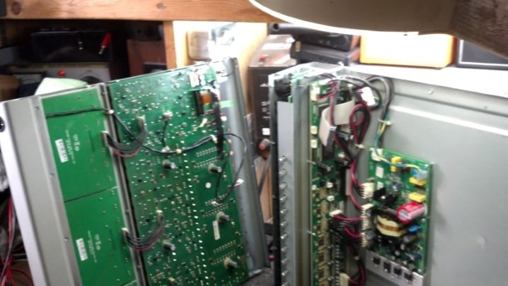
Reassembling the panels together is best done with the unit on its side.

.

Having the unit on its side allows access to all the internal cabling that needs to be reconnected. Glad that we had all the pictures!

.

Some of the small cables need to be reconnected at the last step as they are barely long enough to reach their destination.

.

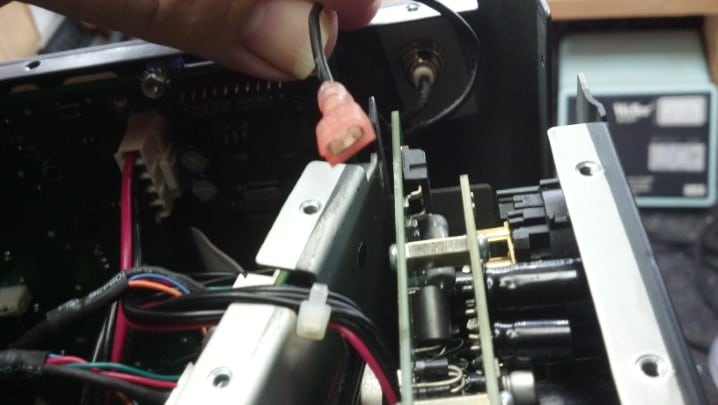
Oh, and here’s that chassis ground terminal. We got it apart somehow…

.

So here we see it almost mated. This step was completed with some very long needle nosed pliers.

.

With the LCD cleaned, this unit appears ready to test again.

.

All functions work. All lights light up. Life Is Good!

.

Thanks for reading all the way to the bottom!

CONTACT – David Latchaw EE
281-636-8626

Shure 55S Microphone Rescued from the Dumpster

Dr. Shoen’s girlfriend at the time found this microphone in a dumpster behind a church. What did he really find, and could it be more than a theatrical prop onstage? The Unbrokenstring Crew goes to work!


Shure Brothers built this iconic microphone at the factory in Evanston, Illinois in the years between 1951 and 1961. The art deco design is recognized around the world as “The Elvis Microphone.”


The 55S is a smaller version of the Model 55 Shure Brothers microphone first produced in 1939.


Unidyne is a term coined to reflect that a single (unitary) microphone diaphragm is employed. The moving coil technique employed to convert sound pressure into electricity makes this a dynamic microphone; Thus we have the word “Unidyne.”


Units with the ON/OFF switch were produced after 1961


The silk wind screen is badly deteriorated. The microphone makes a loud ‘clunk’ noise when it is moved. We need to look inside.


Four screws allow the halves of the microphone body to be separated.


Inside the microphone, we see the element at the top and a multiple-impedance transformer on the bottom.


Two screws hold a bracket that retains a foam vibration dampener in place, which has long since deteriorated and crumbled away. This is the source of our ‘thunk.’


Two more foam vibration dampeners hold the bottom of the element. They are also deteriorated. More ‘thunk.’


The microphone element lifts out easily once the top bracket is removed.


Some of the foam isolation dampeners remain on the bottom two microphone element supports. These are end-of-life and no longer available from Shure.


It is easy to see places where the silk wind screen is missing.


The matching transformer is mounted along with a couple of boxes that retain the now-deteriorated foam vibration dampeners.


Two screws hold these parts in place.


We see the back side of the impedance selector switch in the background, and some set screws in the foreground. What do these do?


The bottom set screw is supposed to hold this spring sheath around the green and orange wires in place.


The top set screw holds the impedance selector switch in place.


We need to take everything out.


The spring sheath runs through the base of the microphone and protects the wires as the microphone is flexed at the joint.


Inside the top of the microphone case we find this sticker, which records the patent numbers employed in the design of this microphone.


The pivot between the microphone and base needs to come apart for cleaning and adjustment.


This screw can be adjusted to set the stiffness of the microphone head relative to the base.


Graphite washers ride between the moving parts for lubrication.


A dent in the body of the microphone needs to be removed. Yes, I’m using my luthier’s hammer to pound out the dent.


Can you see where the dent was?


The old silk wind screen was glued inside the case of the microphone.


Acetone will dissolve the old glue. It will also dissolve silk, turning this cleanup step into a blue sticky ‘hot mess.’


But a little patience and perseverance yields a clean microphone case.


Warning – Skeleton Shot! I’ll betcha that you have never seen a microphone like this.


We found some sheer blue silk fabric for the wind screen. This brighter blue is not historically correct, as ‘Victoria Blue’ (Pantone 2756) was specified by the factory. However, this blue matches the Shure nameplate and badge.


This is a test.


Fabric is glued to the top and bottom as well as sides of the front half of the microphone enclosure. We will now fabricate a soft pillow to allow the fabric to be ‘blocked’ into place as the glue dries in the front half of the microphone enclosure.


This soft pillow will be fabricated from Oomoo. Yes, the silicon mold-making resin will be just the thing.


Equal parts by volume are mixed.


The mix is poured into the front half of the microphone. A plastic sheet protects the microphone shell from the casting material. The Oomoo silicone mold material won’t hurt the microphone shell, but I don’t want to risk contaminating the microphone shell and possibly compromising the glue adhesion later.


And here is our pillow!


We don’t want the pillow to deform the fabric, so these high points are removed by hand with an Exacto knife.


Here is the finished pillow inside the microphone shell.


And here is the fabric, glued and blocked into the microphone shell.


Time to reassemble. The moving joint is reassembled and the cable from the base to the enclosure is reinstalled.


The spring around the cable is held in place with the set screw, as we discovered earlier. This is a nice view of the fabric in the back shell of the microphone. This piece is just a flat rectangular sheet stretched across the back, so it’s easy to glue in place by hand without a block.


The joint is back together. No lubrication is necessary as the graphite washers are doing their job.


A smooth, firm grip at the joint is established before installing the lock nut.


This is what the spring protecting the wires is supposed to look like.


The microphone element works, but I couldn’t resist taking a look at the technology behind US Patent 2,237,298. The hemispherical shell on the back of the element helps establish the cardioid pickup pattern of the element.


I fabricated new foam vibration dampeners, which are installed in three places. The matching transformer assembly goes back where it belongs.


The microphone element is reinstalled where it belongs and wired in. This is now a working microphone. The covering on the microphone element is actually the same material used for vintage silk stockings a.k.a. nylons.


A set of four matching screws are fitted and finished to hold the two halves of the microphone enclosure together.


Pretty spiff!


Thanks for reading all the way to the end!

CONTACT – David Latchaw EE
281-636-8626

Boss DD-20 GigaDelay Pedal Needs Direction

Every function on this pedal works properly.  Except, the user cannot select menu functions without a lot of hassle.  And, the delay time can only be increased, not decreased.  Can the Unbrokenstring Crew decode the mystery and make this unit a little less of a pain in the rear to use again?

The unit turns on and works, but the delay time knob only increments.  This makes it almost impossible to select any function or mode unless the user spins the knob all the way around to wrap back to the beginning of the menu.  And there is, like, three hundred menu items.


Everything is accessible from the bottom.  The vertical strips are Velcro hook material, to hold the pedal in place on the pedal board.


The black plastic rectangle on the left is a battery box.  On the right is a stack of circuit boards.


Removing the circuit boards involves removing the nuts on these jacks.


The ribbon cables interconnect the two main circuit boards.


The metal piece around the jacks is really part of the noise shielding of the box.


We can tip out the bottom board now that the jacks and power adapter jack is free from the rear panel.


Interestingly, this little crescent moon-shaped piece is a bushing that makes a small hole out of a large one.  This may have been a design feature for another model of pedal, or, more likely, the result of an engineering change.  Or, my favorite theory, a design screw-up.


Back in the early days of electronics, stiffened cardboard was coated with wax to make insulating sheets called ‘fish paper.’  Nowadays, we have synthetic equivalents.  This insulating sheet separates the two circuit boards.


To gain access to the top circuit board, we need to remove the control nuts on the top side.  This is the knob for the delay select function.  The knob works fine, the function it performs does not.


This plastic bushing covers a larger hole and allows the knob to be recessed below the plane of the top panel.


These other controls are more conventional in their mounting scheme.  Those hex drive screws are for looks, and only hold the bezel down on the top of the pedal enclosure.  We don’t have to mess  with them today.


At long last, we are able to remove the upper circuit board.


We already have a pretty good idea that the rotary encoder for the delay function is not working properly.  To verify that, the unit is partially reassembled for electrical test.  The cardboard is more insulating material to keep everything from shorting out.  Kinda like home-made fish paper.


The unit is running and the oscilloscope can tell us if the two phases of signal are coming from the rotary encoder.  The answer is, one phase is missing.  Thus, the rotary encoder can only appear to electrically ‘spin’ in one direction.


So, it’s time for the old rotary encoder to come off the circuit board.  A soldering iron will melt the solder and this Solda-Pullit will remove the molten solder.


The new rotary encoder is installed, as shown.  This rotary encoder also has a built-in momentary switch that is actuated when the shaft is pushed down towards the circuit board.  Or, in use, when your foot taps the knob while playing.


Pretty nice workmanship, wouldn’t you say?


Re-assembly is the reverse of dis-assembly.  There are a lot of parts here, so this unit will go back together with the help of all the pictures we took earlier.


The insulative sheet goes here.


The bottom assembly goes here, with the requisite white cables.  Don’t forget to re-install the little crescent-moon-shaped piece where the connectors poke through the back panel.  I did, the first time.  Oh, yeah, and the metal shield, too.


Many of the Boss pedals use this barrel connector for power.  The shell of the pedal housing slide into the slots molded in the connector to firmly hold the power connector in place.  Note that not all barrel connectors have these slots.  If you ever replace a Boss pedal power connector, verify that the replacement part has the slots.


This is a little better shot that shows the proper orientation of the shield plate.  The little sharp fingers around the outside edge should point away from the middle of the pedal, so that they can ‘bite’ into the pedal housing.


The red and black cable carries power from the internal battery box that we saw in the picture above.


The unit is cleaned up and all the knobs reinstalled.  Ready for test!


All functions work flawlessly, PLUS the rotary delay time knob both increases and decreases delay time and allows the user to scroll up and down through the menus.  I think we’re done here!

Thanks for reading all the way to the end!

CONTACT – David Latchaw EE
281-636-8626

TC Helicon VoiceLive3 Pedal Refurbishment

A lot of capable technology lives in this device.  However, if the musician can’t select a configuration because the big rotary selector knob broke off, then it’s e-waste.  Can the Unbrokenstring Crew bring this pedal back from the dumpster?

Pedals live on the floor, and there is plenty of dust to attest to to the fact that this unit has been working hard exactly where it was born to be.  No harm in cleaning and detailing this unit before we’re through!


The main issue here is the broken rotary encoder.  We have the knob, but not the shaft.


Time for a quick tour before we begin.  This pedal serves both vocal and instrument duties.  Flexible monitoring options are available, as well as 3.5mm stereo headphones out and line-in capability.


Separate paths are maintained through the unit for vocal and instrument signals.  Stereo effects are available.


Midi, USB in and out, and a power switch complete the rear panel.  That black rectangle above the USB ports is a cleat to tie off the power cord, to make it a little more difficult to pull the barrel plug out of the power jack.


It takes a lot to get into this box.  Let’s start at the bottom.


The bottom lid is off.  So far, so good.


The footswitches are VERY old school, rugged American made switches, proven reliable since the middle of the century.


Let’s remove the sides next.  This bracket on the side panel supports the bottom circuit board.


These are the external screws on the sides.


These are Torx-head cap screws, giving the device a cachet of ‘tamper-proof-ness’ unless you have the right tools.


Next, the rear panel comes off.  More Torx screws.


Under the side plates, metal plates support the unit to make a very strong metal box surrounding everything.


At last, we can get to the next layer.  The unit is still upside down.


I’m documenting where cables go.  This is a front-panel indicator assembly.


More cable documentation.  See the Ruffles potato chip?


Most of these cables will be marked with a Magic Marker to identify them for reassembly.


Next, the front panel is removed.  These knobs pull off.


There are no lock nuts under these controls.  Interesting…


We have a few more screws to keep track of.  Many of these are a certain length, and shall be returned to the right place.


The LCD is tilted back to gain access to a few more Torx cap screws.  Our final objective is in sight!


The broken rotary encoder is on the same circuit board as the LCD.  To minimize stress on the circuit board, the old rotary switch is cut away, leaving the individual leads in place.  These individual leads are much easier to de-solder.


The holes where the new encoder goes are cleaned and ready to go.


This rotary encoder is a special order part.  Not just any component will fit.


This is a workmanship check of the solder-side of the rotary encoder.


And here is the component side.  Again, not just any part will work here.


We can take a break and do the clean-up prior to reassembly.  Compare this with the first picture.  Yes, the LCD window has been cleaned and polished.


Reassembly is the reverse of assembly (wow, that’s profound.)  The correct fasteners must be reinstalled at each step.


Everything is back where it belongs.  Remember the Ruffles potato chip?  That is actually a dab of adhesive that secures the flat ribbon cable.  A dab of silicone will be added in a moment to secure the ribbon cable again to the same spot.


Looking good!  Everything initialized.  The factory reset procedure is complete.


Somehow, I thought that this was an appropriate preset screen to display.  I think we’re done!


Here is a video showing how the rotary encoder works to change presets and configure the unit into different operating modes.

Support this band! – Fake Believe

Thanks for reading all the way to the end!

CONTACT – David Latchaw EE
281-636-8626

Mackie Thump Active Loudspeakers Need Tweeters

Two active loudspeakers have the same problem – the high-frequency driver has quit.  Does the Unbrokenstring Crew have what it takes to get into these loudspeakers and do the repair?

The enclosures of these units are molded from a very durable plastic material.


So are we dancing?


The rear panel has a crossover frequency control, equalization, overall volume, and audio inputs.


The bottom of the real panel has an input power IEC jack and an on/off switch.


The ‘Suggested EQ Settings’ suggests to me that this is a little more consumer than pro.


Perhaps we can gain access to what’s wrong by removing the loudspeaker.  These nice Allen-head machine screws hold the loudspeaker frame to the case.


With the loudspeaker out of the way, we realize that we cannot really get any tools inside to replace the high frequency driver.  We will need to split the case apart, which is no big deal but at least thirty screws are used!  Let’s get the electric screw driver warmed up and get to work.


The first thing to remove is the handles.  This flat-head screw comes out with the aid of a magnet.


Inside the handle, a nut falls out when the screw is removed.  I’ve retrieved the nut with a magnet.


The nut is held in place in this molded socket.  This may be interesting to reassemble.


This one foot long screw driver bit will allow us to reach all of the screws.


Some of the screws are long.


Some of the screws are shorter.  We make note where they all go.


Here is the foot-long screw driver bit at work.


There are screws holding the case halves together underneath the plate of the amplifier.  Off it comes!


More screws come out.  Glad I got this long bit!


The plate that the amplifier is mounted on is gasketed in place with this L-shaped plastic strip on two sides.


At last, we are in!  The two sections of the enclosure come apart.


And here is the high frequency driver that needs replacement.


To completely separate the two halves of the case, this cable to the pilot light can be removed.


These drivers are held in place with four screws.


Interestingly, the voice coil inside the driver is intact, yet the unit did not work.  This tells us that the voice coil had separated from the diaphragm.


The exact replacement, like the original unit, is made in China.


The new driver is installed with four screws.


All of those screws go back in where they came from.


And there are a lot of screws!


I used blue tape to keep the nuts captive while the handles were reinstalled.

The handle screws are easily tightened as the nuts are held captive in the plastic socket.


Now that the handles are tightened down, the blue tape keeping the nuts in place can be removed.


A little originality is necessary to finish the job.


At last, these units are ready for testing and return to service!

Thanks for reading all the way to the end!

CONTACT – David Latchaw EE
281-636-8626