Boss DD-20 GigaDelay Pedal Needs Direction

Every function on this pedal works properly.  Except, the user cannot select menu functions without a lot of hassle.  And, the delay time can only be increased, not decreased.  Can the Unbrokenstring Crew decode the mystery and make this unit a little less of a pain in the rear to use again?

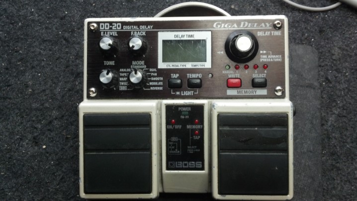
The unit turns on and works, but the delay time knob only increments.  This makes it almost impossible to select any function or mode unless the user spins the knob all the way around to wrap back to the beginning of the menu.  And there is, like, three hundred menu items.


Everything is accessible from the bottom.  The vertical strips are Velcro hook material, to hold the pedal in place on the pedal board.


The black plastic rectangle on the left is a battery box.  On the right is a stack of circuit boards.


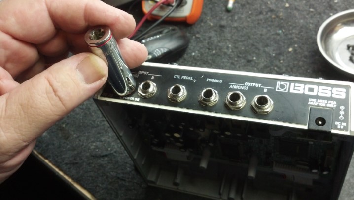
Removing the circuit boards involves removing the nuts on these jacks.


The ribbon cables interconnect the two main circuit boards.


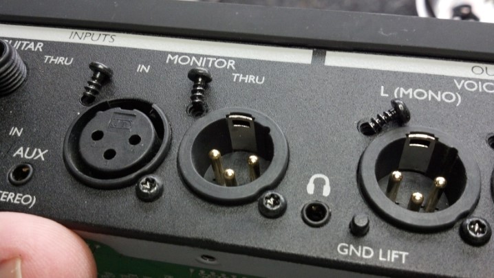
The metal piece around the jacks is really part of the noise shielding of the box.


We can tip out the bottom board now that the jacks and power adapter jack is free from the rear panel.


Interestingly, this little crescent moon-shaped piece is a bushing that makes a small hole out of a large one.  This may have been a design feature for another model of pedal, or, more likely, the result of an engineering change.  Or, my favorite theory, a design screw-up.


Back in the early days of electronics, stiffened cardboard was coated with wax to make insulating sheets called ‘fish paper.’  Nowadays, we have synthetic equivalents.  This insulating sheet separates the two circuit boards.


To gain access to the top circuit board, we need to remove the control nuts on the top side.  This is the knob for the delay select function.  The knob works fine, the function it performs does not.


This plastic bushing covers a larger hole and allows the knob to be recessed below the plane of the top panel.


These other controls are more conventional in their mounting scheme.  Those hex drive screws are for looks, and only hold the bezel down on the top of the pedal enclosure.  We don’t have to mess  with them today.


At long last, we are able to remove the upper circuit board.


We already have a pretty good idea that the rotary encoder for the delay function is not working properly.  To verify that, the unit is partially reassembled for electrical test.  The cardboard is more insulating material to keep everything from shorting out.  Kinda like home-made fish paper.


The unit is running and the oscilloscope can tell us if the two phases of signal are coming from the rotary encoder.  The answer is, one phase is missing.  Thus, the rotary encoder can only appear to electrically ‘spin’ in one direction.


So, it’s time for the old rotary encoder to come off the circuit board.  A soldering iron will melt the solder and this Solda-Pullit will remove the molten solder.


The new rotary encoder is installed, as shown.  This rotary encoder also has a built-in momentary switch that is actuated when the shaft is pushed down towards the circuit board.  Or, in use, when your foot taps the knob while playing.


Pretty nice workmanship, wouldn’t you say?


Re-assembly is the reverse of dis-assembly.  There are a lot of parts here, so this unit will go back together with the help of all the pictures we took earlier.


The insulative sheet goes here.


The bottom assembly goes here, with the requisite white cables.  Don’t forget to re-install the little crescent-moon-shaped piece where the connectors poke through the back panel.  I did, the first time.  Oh, yeah, and the metal shield, too.


Many of the Boss pedals use this barrel connector for power.  The shell of the pedal housing slide into the slots molded in the connector to firmly hold the power connector in place.  Note that not all barrel connectors have these slots.  If you ever replace a Boss pedal power connector, verify that the replacement part has the slots.


This is a little better shot that shows the proper orientation of the shield plate.  The little sharp fingers around the outside edge should point away from the middle of the pedal, so that they can ‘bite’ into the pedal housing.


The red and black cable carries power from the internal battery box that we saw in the picture above.


The unit is cleaned up and all the knobs reinstalled.  Ready for test!


All functions work flawlessly, PLUS the rotary delay time knob both increases and decreases delay time and allows the user to scroll up and down through the menus.  I think we’re done here!

Thanks for reading all the way to the end!

CONTACT – David Latchaw EE
281-636-8626

TC Helicon VoiceLive3 Pedal Refurbishment

A lot of capable technology lives in this device.  However, if the musician can’t select a configuration because the big rotary selector knob broke off, then it’s e-waste.  Can the Unbrokenstring Crew bring this pedal back from the dumpster?

Pedals live on the floor, and there is plenty of dust to attest to to the fact that this unit has been working hard exactly where it was born to be.  No harm in cleaning and detailing this unit before we’re through!


The main issue here is the broken rotary encoder.  We have the knob, but not the shaft.


Time for a quick tour before we begin.  This pedal serves both vocal and instrument duties.  Flexible monitoring options are available, as well as 3.5mm stereo headphones out and line-in capability.


Separate paths are maintained through the unit for vocal and instrument signals.  Stereo effects are available.


Midi, USB in and out, and a power switch complete the rear panel.  That black rectangle above the USB ports is a cleat to tie off the power cord, to make it a little more difficult to pull the barrel plug out of the power jack.


It takes a lot to get into this box.  Let’s start at the bottom.


The bottom lid is off.  So far, so good.


The footswitches are VERY old school, rugged American made switches, proven reliable since the middle of the century.


Let’s remove the sides next.  This bracket on the side panel supports the bottom circuit board.


These are the external screws on the sides.


These are Torx-head cap screws, giving the device a cachet of ‘tamper-proof-ness’ unless you have the right tools.


Next, the rear panel comes off.  More Torx screws.


Under the side plates, metal plates support the unit to make a very strong metal box surrounding everything.


At last, we can get to the next layer.  The unit is still upside down.


I’m documenting where cables go.  This is a front-panel indicator assembly.


More cable documentation.  See the Ruffles potato chip?


Most of these cables will be marked with a Magic Marker to identify them for reassembly.


Next, the front panel is removed.  These knobs pull off.


There are no lock nuts under these controls.  Interesting…


We have a few more screws to keep track of.  Many of these are a certain length, and shall be returned to the right place.


The LCD is tilted back to gain access to a few more Torx cap screws.  Our final objective is in sight!


The broken rotary encoder is on the same circuit board as the LCD.  To minimize stress on the circuit board, the old rotary switch is cut away, leaving the individual leads in place.  These individual leads are much easier to de-solder.


The holes where the new encoder goes are cleaned and ready to go.


This rotary encoder is a special order part.  Not just any component will fit.


This is a workmanship check of the solder-side of the rotary encoder.


And here is the component side.  Again, not just any part will work here.


We can take a break and do the clean-up prior to reassembly.  Compare this with the first picture.  Yes, the LCD window has been cleaned and polished.


Reassembly is the reverse of assembly (wow, that’s profound.)  The correct fasteners must be reinstalled at each step.


Everything is back where it belongs.  Remember the Ruffles potato chip?  That is actually a dab of adhesive that secures the flat ribbon cable.  A dab of silicone will be added in a moment to secure the ribbon cable again to the same spot.


Looking good!  Everything initialized.  The factory reset procedure is complete.


Somehow, I thought that this was an appropriate preset screen to display.  I think we’re done!


Here is a video showing how the rotary encoder works to change presets and configure the unit into different operating modes.

Support this band! – Fake Believe

Thanks for reading all the way to the end!

CONTACT – David Latchaw EE
281-636-8626

Peavey MX Combo Amp Rescued from a Bad Amp Tech

This combo amp had lived a hard life and had finally quit.  Grandpa wanted his grandson to get the amp fixed so that they could jam together again.  Could The Unbrokenstring Crew bring this unit back to life?
 We begin with a quick tour of the rear panel.  The ground switch is a tip of the hat to the Old Days of two wire AC.


 The foot switch plugs in where the REMOTE SWITCH jack is coming loose.  This gets fixed.


 I’m surprised that this hadn’t ripped loose.  The whole connector wil be replaced.


 Name, Rank, and Serial Number, please!


 What have we here?  We found grandpa’s stash.


Let’s get this line cord wired correctly.  Do you know what’s wrong?


 The black wire goes under the brass screw. “Black on brass will save you ass.”  You’re welcome.


 The reverb tank connects to the main circuit board with this connector.


 Even after all this time, the high voltage capacitors are still charged.  Woah!  This is my discharge wand at work.


 Our first mystery… where does this nut go?


 This is a fuse.  No, you think that it is a piece of 16AWG wire, but it is a fuse.  Or, it is where a fuse goes.


 And here, someone was tired of the fuses falling out of the holders, or what was left of the holders.


 The heat from the flow of current has wreaked havoc on this solder joint.


 This probably smelled bad when it was hot.


 Now that the introductions are out of the way, we need to start replacing this nonsense.


 These are commercial fuse holders.  These will replace all of the preceding nonsense.


 The plan will be to install these new fuse holders at a spot in the circuit where they will be functional, yet out of the way.


 The new fuse holders are held down with a screw.  This hole is where the screw goes.  Here goes!


 Another hole is drilled for another fuse holder.


 This hole is in the center of a trace.  We won’t miss that copper.  Much.


 Insulating nylon nuts and bolts are used to keep the new fuse holders in place.


The traces in the burned circuit boards are replaced with this Teflon-covered wire.


 Everything is now stuffed back into place.  Not too shabby, if I do say myself.


Turning our attention to the rear panel, your sharp eyes may recognize this connector as a MIDI female panel connector.


 To keep the connector hardware in one place, some of this Thread Locker is all we need.


 We have the original foot switch.  It needs a new cable, with a connector to match what we just installed in the amp.


 This MIDI cable will be repurposed to replace the cable on the footswitch assembly.


 We don’t need this connector.  Instead, this end of the cable will be wired to the switches themselves.


 The new cable is soldered directly to the switches  Note the strain relief installed to the right of the picture..


 This pedal is ready for action once again!


 The amp is reassembled and is ready to go!


 The four hour burn-in test is underway.  I think we have rescued another vintage Peavey amp!

Thanks for reading all the way to the end!

CONTACT – David Latchaw EE
281-636-8626

Ibanez Compressor Pedal CP10 Repair

Mysteriously, this pedal just went mute while playing.  Can the Unbrokenstring Crew get it going again?

I find this to be a unique design.  But I cannot help but think that the assumption was made that everyone uses their right foot to run the pedal.  Using your left foot is a little awkward.


Let’s make a quick tour of the unit.  The pointers on these molded knobs are actually easy to see when the unit is on the floor.  The LED indicates that the unit is in circuit and active.


Pushing this little tab out allows the pedal pad to open.


The 9v battery goes here.  This switch is actually soldered to a small circuit board underneath.


Removing the bottom cover exposes the circuit board.  The black shiny sheet in the middle is an insulator.


The circuit board tips out like this.  But, there’s more!


The controls are located on a smaller circuit board underneath.  Out it comes!


These bushings align the shafts of the controls in the holes.  They just push in like grommets.


Now we can get to everything.  The switch itself is left installed in the housing.


Troubleshooting begins, using my massive Marshall Stack as an output indicator.


The signal is traced to here.  And then the signal disappears.  Can you see it?  I can’t either.


This capacitor is open-circuit.  No signal shall pass this way again.


Here is a replacement.


The replacement goes here.


The new cap is soldered in and the flux is cleaned away from the board.  Because I’m OCD like that.


Everything is working again.  We’ll put this unit back together and do a final test!


This looks no different than the first picture.  Except, this one works.

Thanks for reading all the way to the end!

CONTACT – David Latchaw EE
281-636-8626

Some Advice for Musicians Whose Gear Was Water-Damaged by Hurricane Harvey

Shortly after the Shuttle Explosion in 1986, the computers onboard the Challenger orbiter were retrieved from the floor of the Atlantic Ocean.  Each ‘set’ of boxes was sent to a different NASA Center for analysis.  One set came into the IBM Federal Systems lab in Clear Lake, Texas, where we dried, partially disassembled, and reassembled the hardware in hopes of recovering any clues regarding the accident.  I was the sub-contract manager at IBM at the time and was tasked with engineering support for the effort, including electrical test, micro-soldering, cable assembly, and such.  I am proud to report that the unit came back to life after two weeks of salt water immersion, and the data in the memory core was intact up to the point that vehicle power was lost; That information contributed greatly to the accident timeline.

So I want to weigh in on some strategies for musicians who found that their gear was water-damaged in Hurricane Harvey, which is still affecting Coastal Texas as I write this.  Let’s get going!

  1. Don’t turn anything on to see if it still works.  Odds are, it won’t.  And it won’t because you turned it on, dumbass.
  2. Unplug everything.  Your power is probably off anyway, but it never hurts to be sure.
  3. Remove ALL the batteries.  This includes tuners of all kinds, even the ones built into an acoustic guitar, guitar pedals and effect units, portable recorders, laptops, microphones, everything.  Same process as when your cell phone falls in the toilet.
  4. For all stringed instruments, slack the strings.  You don’t have to remove them, but just remove the tension.  Loosen the pegs on your violins/violas/cellos/basses to slack the strings; don’t bother with the fine tuners.
  5. For instruments with truss rods in the neck (guitars, basses, etc.) slack the truss rod.  Just a half a turn in the direction of ‘more loose, not more tight’ is the way to go.  For most instruments, that’s counter-clockwise.
  6. Drum heads on banjos and drum kits should be slacked as well, if the shell was wet.
  7. Many woodwinds will be OK if you were treating them with sweet oil on a regular basis.  The case will be in worse shape than the instrument.  Wipe everything with a dry towel and let it air dry for a week or two.  Inspect any pads and remove the reed; the reed will need to be replaced anyway unless you use synthetic reeds.

Now that everything is stable, let’s consider the recovery options.  The challenges we face are as follows:

  • Acoustic instruments made of wood are not damaged by a little water.  A lot of water will swell the wood and stress/break the glue bonds.  The sooner the liquid water is removed from the surface of the wood, the sooner we can begin the process of drying the instrument.  Wipe it down with a dry towel, inside and out.  There are instances of classical guitars stored in a basement in Central Europe that had absorbed TWICE THEIR WEIGHT in water that were successfully dried and returned to play-able condition.
  • Acoustic instruments made of wood ARE damaged by too much drying.  Shrinkage causes the wood to pull away from glue bonds and pull away from itself e.g. crack.  This Peavey neck became over-dried in hot attic:Fortunately, we have (and will continue to have) PLENTY of humidity so a good, slow, open-air drying over the next couple of weeks will cause the least damage to our acoustic instruments.  Resist the urge to pull out the hair dryer!
  • Solid body instruments are, more impervious to liquid water by virtue of the fact that they are usually finished in polyurethane or other rugged finish.  Again, wipe it down with a dry towel.  We’ll come back to work on the controls in a moment.
  • Martin guitars with the composite bodies, and Ovation guitars with their famous ‘bowls’ may be difficult to recover.  The sound board expands and shrinks at a different rate than the rest of the guitar.  Ovation will (upon request and sufficient $$) replace a wet top with a new one.  The Music Factory in Pearland has done this with a few of their new Ovations following the last hurricane.  I have not spoken with Martin but my guess is, you might have to call them and discuss the options.  Many of the composite/laminate guitars are under $500 which limits the range of repair options.

The areas of concern with our electronics fall into these categories: (1) cabinets and grille  (2) loudspeaker cones  (3) controls and switches.

Note that I did not say anything about the electronics themselves.  Electronic assemblies built after, say, about 1990, are mass produced by a process that uses water as a cleaning solvent.  This is called ‘aqueous cleanup’ and is almost ubiquitous in all electronic assembly shops around the world.  Your electronics will fare fare better in the flood than you think, particularly if we don’t energize them while wet.

  1. Let’s start on the cabinets and grilles.  Remove the grille and dry what you can with a towel.  The frame is almost always wood, and the fabric is almost always a synthetic.  The wood should be allowed to dry slowly over the next couple of weeks.  Do not apply any heat.  The frame may still warp a little, but we will deal with that when we reassemble the cab.
  2. Wipe all water from the cabinet, paying particular attention to the inside and bottom of the cabinet.  Remove the reverb tank, if it is present, and set aside.  Again, with the cabinet, a slow dry may be all it needs.  If the cabinet is made from particle board, you will see swelling which may spoil the appearance of the unit.  The particle board will never be as strong as it was before it got wet.  If your cabinet is particle board, you might convince yourself that Harvey has given you permission for an upgrade to a pine or plywood cabinet.
  3. Carefully remove any remaining liquid water from loudspeaker cones.  Let everything dry out for a week or two.  Then GENTLY push the cone evenly forward and back and listen for any rubbing or scratching noises.  If you don’t hear any noise (called ‘motor noise’) you may be OK.  Unfortunately, some magnets have a high concentration of metallic iron, which will rust (and swell) in the presence of moisture.  If the rusting is bad enough, the loudspeaker needs to be reconed or replaced.

Let’s take a look at the electronics.  The controls and switches on guitars and the controls and switches on amplifiers are treated in a similar manner.  Circuit boards and wiring harnesses are not hard to clean up if you are handy.  If you are comfortable disassembling your amp head or accessory, then Read On.  If not, there are many shops (not just mine) that are on Facebook that are competent to perform these repairs.  I am detailing these procedures so that the do-it-yourself-er can have some confidence to proceed, and also so that the non-do-it-yourself-er can speak competently with your chosen tech.

  • Compressed air is your friend.  The air blast will remove any liquid water present.  After disassembling your gear, get compressed air underneath components, connectors, transformers, anywhere there is a place where water can reside.  Those little cans of ‘electronic dusters’ are cool but expensive.  Pull out the air compressor.  Pull the bottom plate off your pedals to gain access to anywhere water may be lurking.  Remove those pick guards and blow everything dry.  Open up those battery boxes (you did remove the batteries, didn’t you?)  Dry everything!
  • Switches need a rinse and then lubrication.  I use ‘Blue Shower’ as a rinse, which is for cleaning television tuners.  There are other products that work as well.  Google “CAIG” read up, and go shopping at Fry’s for some of the CAIG products they carry.  Start with the CAIG F5 stuff as a rinse, then the CAIG GOLD stuff as a protector lubricant.  I use the CAIG GOLD product as well as some MIL-SPEC stuff (because I Am Cooler than you and can get MIL-SPEC stuff and you can’t.)
  • Hit the input and output jacks with a little CAIG GOLD on a cotton swab.  This is just good routine maintenance, and is particularly vital now that your instrument may have been wet.
  • For controls that were working fine before the flood, I would just use a shot of the CAIG Fader Lube (same aisle at Fry’s) as a water displacer and a lubricant.  Don’t try to rinse good controls because you may displace the factory lubricant and put it where it may create noise on the resistive element.  Keep It Simple.
  • Cables may be problematic.  My advice would be to toss the wet ones and get new ones.  My reasoning is this: Cables are often the weak link in any setup, even when new.  You know this.  Water will deteriorate cables because it will penetrate each end of the cable.  Copper and its alloys react readily in the presence of water and contamination (dirt from flood waters, for example.)  Also, the connector itself may be compromised by corrosion, as will be the solder joints or compression welds performed when the cable was new.  It will only get worse.  Toss the cables.  Just do it.  Life is too short.
  • For pictures of what I do with controls, check my previous post on https://www.unbrokenstring.com/noisy-controls-in-an-swr-red-head-bass-combo/
  • Most guitar pickups are encapsulated with wax or epoxy.  While the pick guard is off, blow out and dry what you can reach.  There may be some very fine wires exposed where they may be damaged, so don’t go crazy with the towel.
  • Reverb tanks have small transformer wound with small wire, like guitar pickups. Also, the springs are fairly delicate. Do what you can to dry them out before rust and oxidation set in. If they need to be replaced, reverb tanks may be purchased on-line for $30-$40 or so.
  • The CAIG Fader Lube is a very good lubricant for tuning machines.  While you’re at it, give them a shot of lube, directing it in such a way that it can enter the tuning machine.  Rinse.  Repeat.

UNDER NO CIRCUMSTANCES USE WD-40 ON YOUR GEAR.


WD-40 is good for your wet car ignition, but it has fish oil in it, which is just plain nasty considering that this is the 21st century and you can get modern products for your equipment.  Some people swear by WD-40, and I use it on lawn equipment and tools.  When people use it on electronics and musical instruments, I swear AT them.

Now that you are Poseidon and can command water to go away, here’s another tip.  If your flood water was muddy or contaminated, you can use clean water at anytime on most electronics.  This includes switches, controls, circuit boards, and all the stuff we’ve mentioned so far.  Your electronics were built in a factory that used water to clean the final product.  You can do this, because you know how to remove water.  And you are Poseidon.

FYI, full disclosure – I don’t own stock in CAIG.  However, their products are Top Drawer and are available at Fry’s in the hard-hit Southeast Houston area where I work and live.  In the Northwest part of town, ACE Electronics has the Blue Shower and equivalent lubricants.  These are the products that are available NOW (er… when the power comes back on and the roads are passable..) and are not vaporware.  Just tryin’ to help.

Again, there are several VERY COMPETENT shops in the Houston area that are willing and able to assist with an attempt to recover water damaged gear.  Check the musician groups on Facebook, and do a search for ‘repair’ before you post anything.  Turns out, some guy posts the same question every week or so, looking for a good repair shop.  And the same answers keep coming up again and again.  Don’t be that guy.  I am booked solid out through the end of September and may not be able to take on your work right away.  If you care to contact me directly, I can discuss some options and recommend some Good People who can get you going again.

Thanks for reading all the way to the end!

CONTACT – David Latchaw EE
281-636-8626