MusicMan RD50 Combo Amp Repair and Inspection

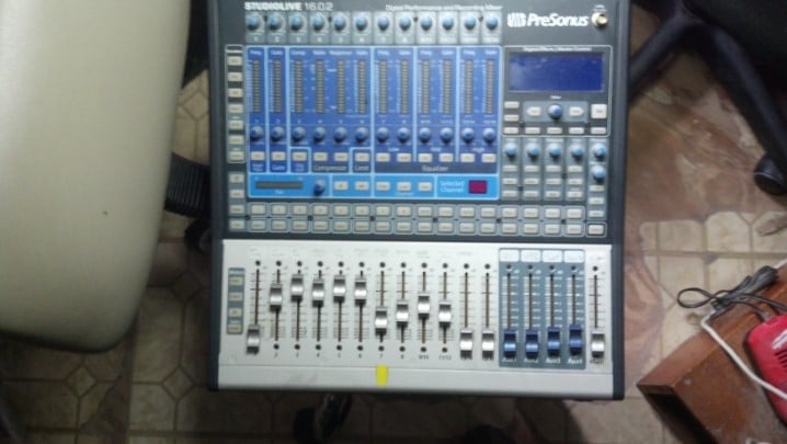
AJ played this wonderful MusicMan combo amp, until it quit suddenly. He was aware of the Big Names in the music business that repaired these, but was there anyone local? D’oh!

.

As you might expect, this combo has one 12 inch loudspeaker and has a fifty watt Class AB push-pull pair of 6L6 tubes. One vacuum tube serves as a preamp, and the rest of the amp is built with solid state techniques.

.

This looks a lot like a Fender amp, doesn’t it? Leo Fender had sold the Fender company to CBS, but wanted to continue making instruments and amplifiers despite a non-compete agreement that he was required to sign as part of the deal with CBS.

.

So the MusicMan amps were born. The Mid-shift switch indicates a slightly different tone stack design.

.

IIRC, production was shifting away from the Fullerton factory to Anaheim, with offices in La Brea California.

.

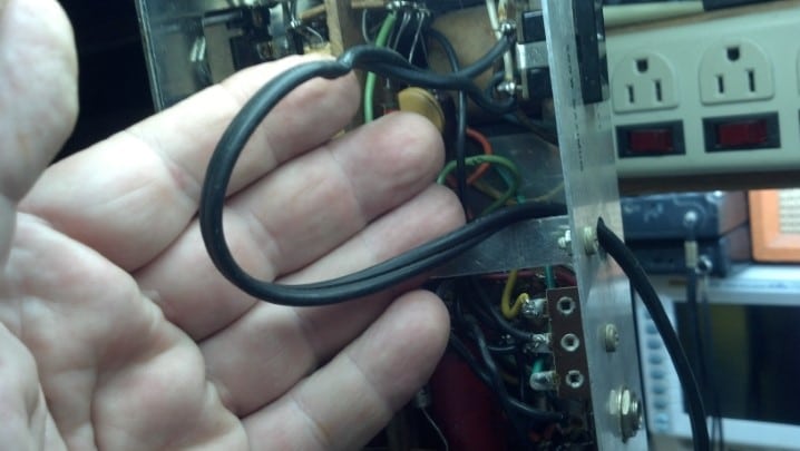
The rocker switch for the ground select function and a three wire power cord is evidence that the older design of Fender amps was changing to meet modern regulatory requirements.

.

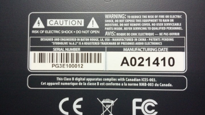
Of course, model numbers were entirely new, and serial numbers had little resemblance to the old way of doing things.

.

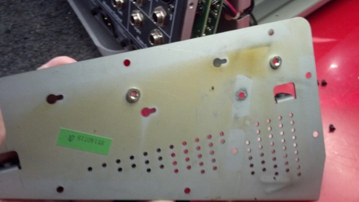
I have no idea what the paper label to the right is for. Any ideas, anyone?

.

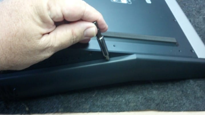
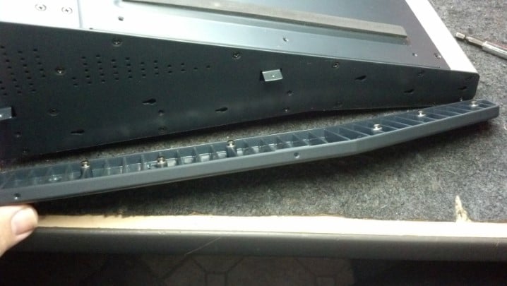
The chassis is sound, if not a little cosmetically ‘challenged.’ We can blame the humid Gulf Coast environment.

.

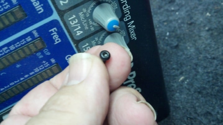
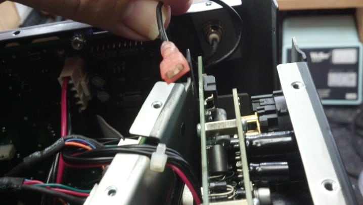
Another change from the Old Fender was this pilot light, which consists of a neon bulb and a limiting resistor. The package is held in with a push nut.

.

Yet another thing we don’t see here is the iconic brass sheet upon which most of Fender’s controls and jacks are traditionally mounted.

.

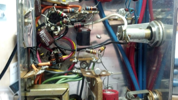
The wire harness dress is excellent as is the workmanship. The black switch is the Tone Shift switch seen earlier on the front panel.

.

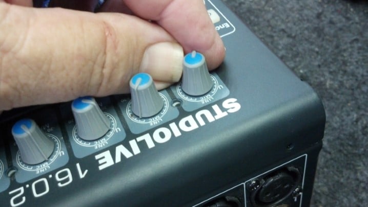
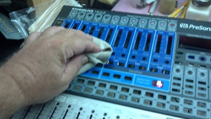
These front panel controls work smoothly and are noise-free.

.

The Bright/Normal switch is found next to the input jack.

.

The dual-section 12AX7 lives here. This amp has been re-capped, including cathode bypass capacitors and all electrolytics. I’m not touching any of this!

.

The rear panel jacks are Switchcraft, the best you can get.

.

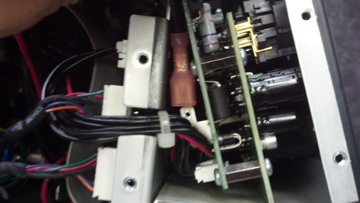
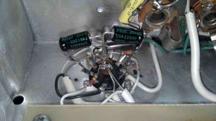
This ‘death’ cap is original. The red paint on the solder joints is an interesting way to indicate that they passed QC. This makes it easier to see where past rework/repairs have been done.

.

The fuse holder held a too-high value 32v automotive fuse. The correct 250vac 3A part is installed.

.

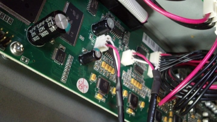
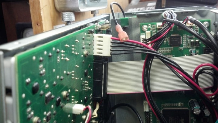
Most of the preamp duties are done with operational amplifiers. Those connectors in a square configuration are for the reverb tank and pedals.

.

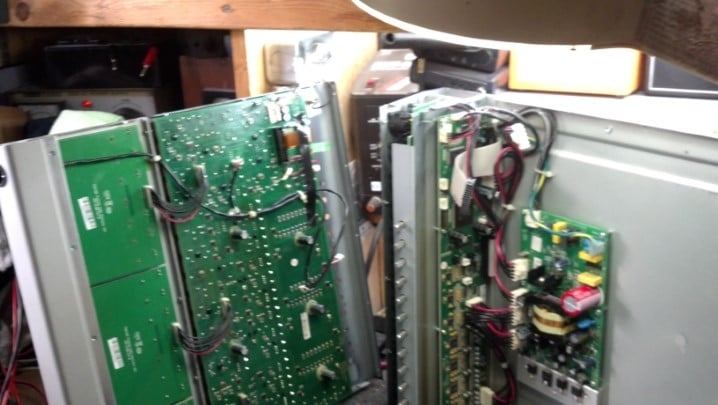
This unit is very well built and maintained.

.

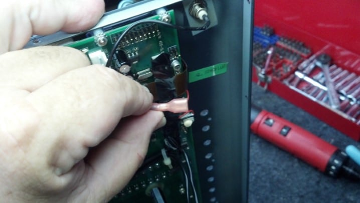
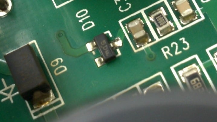
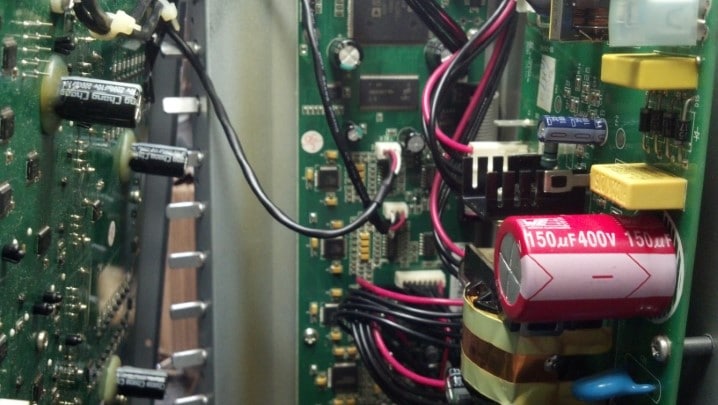
Can you see the problem? The pair of transistors on the pink heat sink form a phase inverter that drives the output tubes. In the 1970s, televisions, ham radio gear, and other consumer electronics were commonly built using ‘hybrid’ techniques e.g. solid state parts with power tubes. Leo Fender knew his TV stuff, and applied that technique in his new line of amps.

.

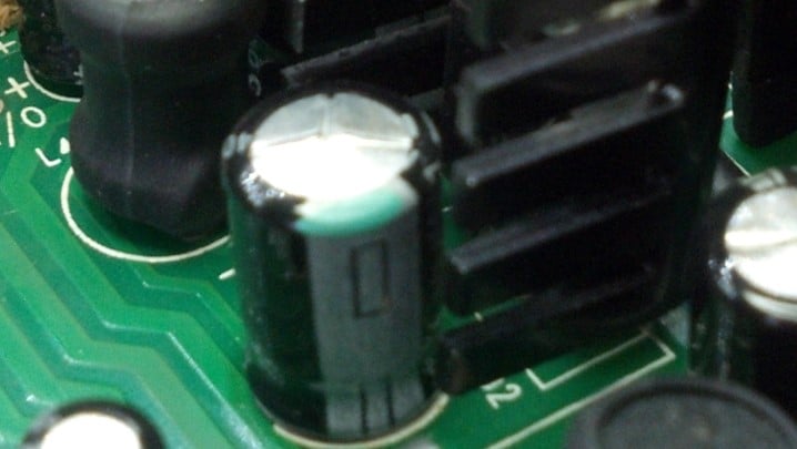
These high powered resistors are part of the phase inverter circuit. They must be matched closely for good performance. Obviously, these are no longer matched.

.

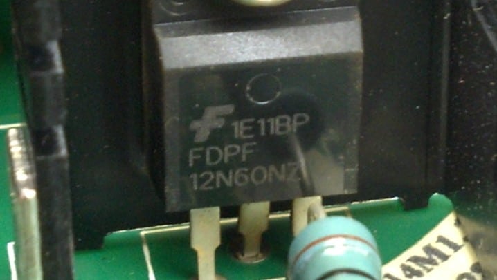
The devices on the heat sink are 75 watt 15 ampere 80 volt power transistors. They should be closely matched for best sonic performance. Also, transistors will drive the next (tube) stage with a bigger voltage swing than two sections of a vacuum tube, because they are inherently lower impedance.

.

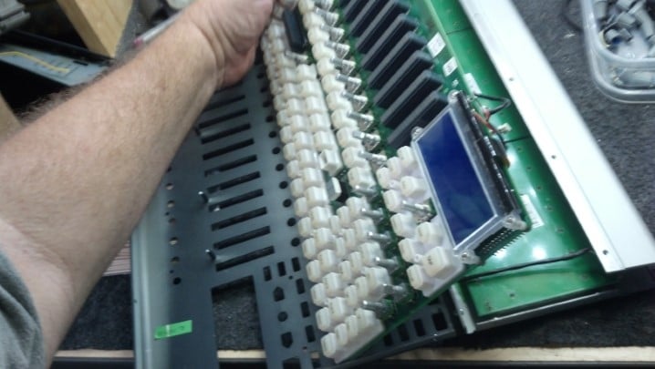
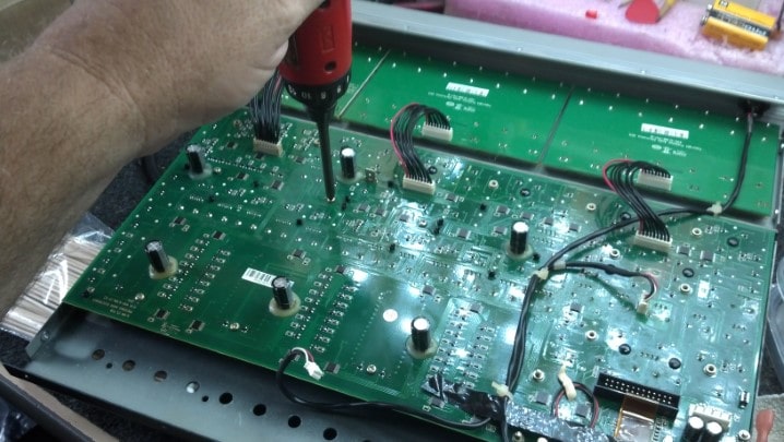
The main board is coming out of the chassis so that we can solder and desolder parts.

.

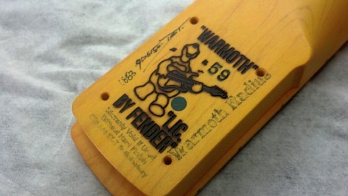
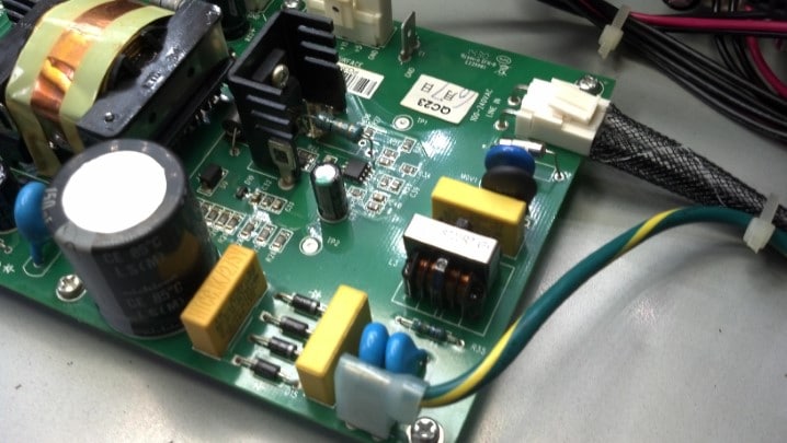
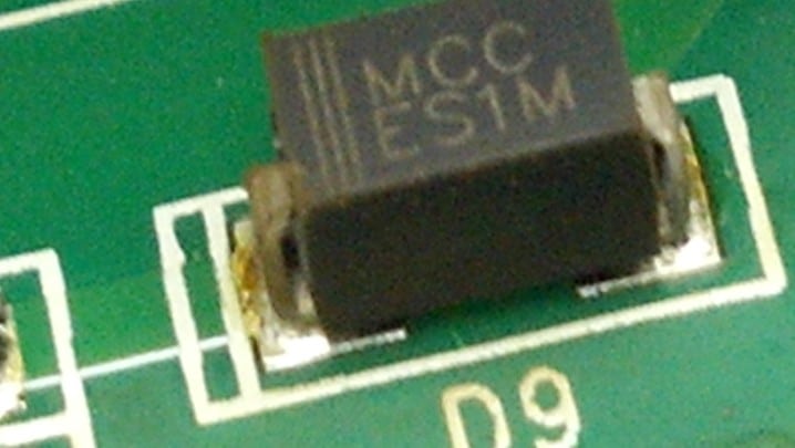
In the late 1070s, circuit board design was performed on computers. Thus, graphical images could be added to the artwork. Also, this circuit board is electrochemically plated tin, which is a fresh new technology not previously seen in Fender products.

.

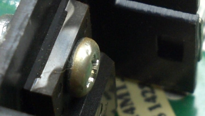
On a lark, we will measure the value of the remaining 6.8 ohm resistor.

.

It reads a little high. No problem. The resistors will be replaced with a matched pair.

.

The old transistors are coming out for testing.

.

The transistor curve tracer shows that this part is good.

.

The other part is shorted internally.

.

The heat sink is removed and the old resistors are desoldered. Here, we’re cleaning up the circuit board where the resistors go.

.

These two parts were sourced from new stock and selected because their value matches better than 0.1%.

.

These transistors were sourced from new stock and were matched on the curve tracer. See the new resistors above and to the left?

.

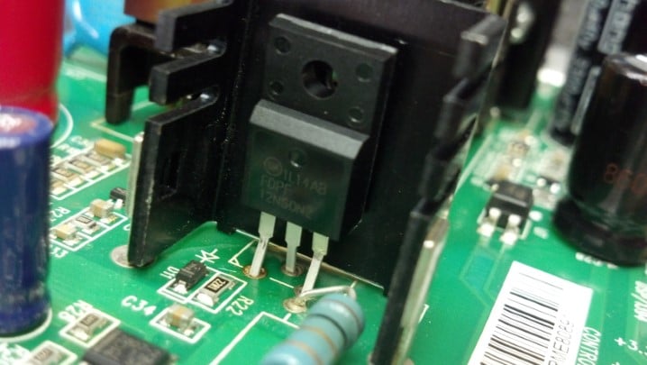
The solid state phase splitter drives the tube stage as it should.

.

The tubes are in and it’s time to fire it up!

.

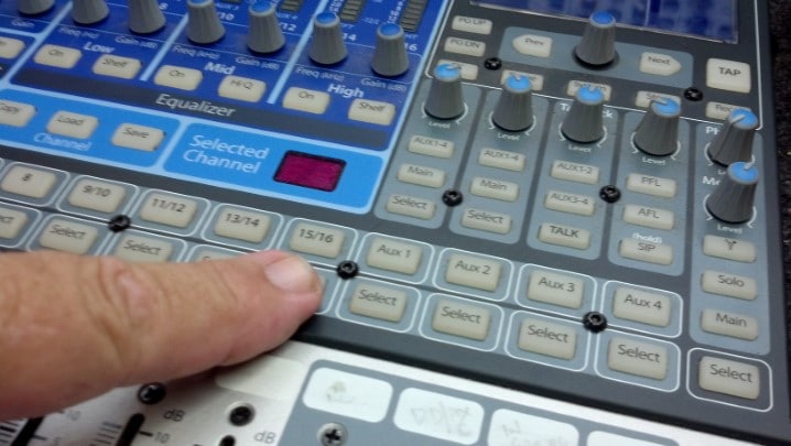
This amp comes with the official MusicMan pedal, controlling reverb and distortion.

.

When a function is selected, the LED comes on. This is nice on a dark stage!

.

This unit is ready to go again!

.

.

Thanks for reading all the way to the bottom!

CONTACT – David Latchaw EE
281-636-8626

Sears Silvertone 1484 Amp Head Refurbishment

Andy found a ‘beater’ Silvertone amp on eBay and was curious if it could be restored. At first look, it was pretty rough. But could the Unbrokenstring Crew work some magic to undo the damage caused by UPS and previous amp techs?

.

Danelectro built these amps for mail order distribution. In the 1960s, Amazon was a river in Brazil and the Internet was a military thing. But the Sears Catalog brought you nearly anything you wanted.

.

The Sears catalog number was the URL of merchandise. With that number, the world was your oyster.

.

The split splined shaft on the reverb was broken, and the original knob was long gone. The control does work electrically, but the reverb function was not functioning. Or something like that.

.

The main volume knob was missing, because the split shaft was compressed and didn’t have enough remaining ‘bite’ to retain the knob. This could be repaired.

.

One of the preamp tubes is a Chinese 12AX7. That tube tested bad.

.

However, the rest of the tubes were in fine shape and were kept in service. By the looks of the power transformer, I believe that this amp was dropped on its end, because the transformer is leaning to the right.

.

One of the preamp tubes is original, a Silvertone 6FQ7, made in U.S.A.

.

The chassis is hand-wired. We are starting at the preamp section. Those brown capacitors are mica capacitors. Wherever two of them are next to each other, they are taped to each other using black electrical tape.

.

The pilot light is good. The red and blue wires to the right are all shielded signal cables. Power wiring is on the left.

.

The transformer on the left is an interstage coupling transformer. Masonite, a pressed fiber board material, is used extensively in this unit. Here a big chunk runs right down the center of the amp chassis, and many terminal strips are riveted to the Masonite for mounting components.

.

The red cylinders are the filter capacitors, and the small silver cylinders are the power rectifiers. Amazingly, the filter capacitors required almost no reforming. Normally, capacitors this old are replaced out-of-hand, but the owner preferred to keep it as original as possible.

.

Each and every capacitor was screened for leakage at working voltage and capacitance value. Do you see the scorch mark?

.

At this end, we can barely see the output transformer, which has been replaced with a service spare part. Apparently the output transformer failed at some point, leaving some scorched areas behind.

.

These blue wires come from the non-functional reverb tank.

.

These wires come from the other end of the reverb tank. So we can guess that the reverb tank failed, and some Jake Leg tech just cut it out of the circuit rather than fix it.

.

So, we will fix it. Note the duct tape holding the whole arrangement together.

.

We find more Masonite under the tape. Each end of the spring in the reverb tank is stretched between the end clips.

.

A second point of contact intersects the spring about an inch away from the end. Note that this contact is bent. This is another indication that the amp was dropped on its end.

.

In the middle of the spring, this wire guys the spring at the center of the tank.

.

So we bend the bent contact so that it pokes into the spring where it belongs. A very high voltage signal, over one hundred volts, is applied to the contacts at one end. The insulating cardboard on each contact keeps the current from flowing through the spring. However, the high electric field induces a mechanical motion into the spring, which is carried through the spring and wiggles the two contacts at the other end. The wiggling contacts act as a variable capacitor. The change in capacitance causes a varying voltage to be produced, which is amplified and sent to the amp. A moving ribbon microphone or condenser microphone works the same way.

.

Simple enough, huh? Speaking of simple, we have Upgraded this reverb tank from duct tape to wire ties. Which is kind of a big deal, if you ask me.

.

The reverb tank lives here. But the chassis is filthy. Now is the time to clean it all up.

.

A rag is soaked with a combination of solder flux remover and furniture polish, which is tough enough to cut through six decades of crud.

.

The reverb tank is suspended over the chassis with this bracket. It just bolts on.

.

A replacement control has arrived. These stamped sheet metal nuts are used to keep the controls in place. The controls are all recessed behind a trim panel. The recessed trim panel makes it a challenge to find knobs that will work on this amp, as we will find out later.

.

Here, the replacement control has been lubricated and will be wired into its new home.

.

The reverb control has an ON/OFF switch that literally disconnects the reverb tank from the rest of the amp. The two terminals on the back of this control are the ON/OFF switch terminals.

.

That sheet metal nut will not take much torque, so it is being tightened by hand.

.

Next, we will replace this two wire line cord with a three wire cord, so no one will be electrocuted if the power transformer insulation fails.

.

Two of the line cord wires go to this convenience outlet. The outlet will remain in place, but will be removed from the circuit.

.

The power switch wiring is being modified to switch only the ‘hot’ wire. The neutral and ground wires will not be switched, per UL requirements. Also, the ‘death’ cap will be removed from the circuit, so that, when it fails shorted, raw 120VAC will not be connected to the chassis. You will find that important if you are holding the guitar at that moment…

.

Let’s see what we can do about wiring in the reverb tank. These blue twisted wires are snaked through the chassis and will be attached to the terminal strip in this picture. Here is another good look at a pair of mica capacitors taped together.

.

The little terminal strip in the middle of the picture has the remnants of the original blue reverb tank wires left from where the previous tech disconnected the reverb tank. So now we know right where to reattach them.

.

Another reason to love eBay is that, from time to time, the Correct knobs can be located. These were surprisingly affordable. Some of the original knobs were repaired with Super Glue and reinstalled.

.

The unit is back together and ready for final test!

.

Finally, the Correct knobs really improve the cosmetics of this fine old amp head. The owner wanted to leave the film of rust on the front of the unit, for that Vintage Mojo look. This head sounds fantastic, but the piezo electric reverb tank sounds like something from a Star Trek special effects soundtrack, which, might be just the sound you want!

.

Thanks for reading all the way to the bottom!

CONTACT – David Latchaw EE
281-636-8626

Fender Blackout Strat Becomes Even More Classic(al)

The original neck on this MIM Black Strat was made from wood that tended to twist when the string tension varied, either because of temperature changes or when employing different string gauges. It’s now time to take this guitar to the next level, and make it an iconic Blackout Strat

.

The neck will be retired to another instrument.

.

This instrument was built in 2006, which happened to be the 60th anniversary of the founding of Fender Corporation.

.

The neck is off and headed to its new home.

.

David Gilmour’s Blackout Strat has a maple fret board. This instrument will get a new maple neck, with a 59 ‘C’ contour and an almost 2 inch wide nut. With light strings, this guitar will feel like a nylon-stringed classical guitar.

.

The aftermarket Fender tuners are lined up with the machinist’s rule and tightened into place one by one.

.

These tuners are ‘locking’ tuners, which positively grip the end of each string in a clamp. This is necessary on this instrument because of the very light gauge strings we will be using.

.

Head stock and nut are ready to go.

.

The middle pickup appears to be not working. Let’s take a look inside.

.

Sure enough, there is a broken wire inside the pickup cover.

.

The break in the wire is literally in the very last turn! So one turn is un-spooled and threaded through the eyelet where it belongs.

.

As was done at the factory, the wire end is pulled through the eyelet a few times and soldered in place.

.

The middle pickup is tested and is right where it should be.

.

The Classic(al) Blackout Strat is strung with 7 gauge strings; Yes, not 12s, not 10s, but with Billy Gibbon’s own Dunlop Reverend Willy Extra Light Electric Guitar Strings, .007-.038. With the proper setup, this instrument has the play-ability and feel of a nylon-strung classical guitar. Thus, we have the Classic(al) Blackout Strat.

.


Thanks for reading all the way to the bottom!

CONTACT – David Latchaw EE
281-636-8626

PreSonus StudioLive 18.0.2 Mixer Is Resurrected from the Dead

Richard relied on this unit for much of his sound, and when it went dark, he had to get it fixed or change his entire setup. Could the Unbrokenstring Crew bring it back to life and preserve Richard’s workflow?

.

Our Cajun neighbors designed and engineered the mixer.

.

Two screws hold on the side trim pieces.

.

Once the screws are removed, the whole trim piece slides to one side and all these machined studs come out of the slotted holes. Nice.

.

These side panels provide most of the mechanical strength of the finished assembly. Lots of little black screws hold them on. The red plastic tray on the right keeps them off the floor.

.

Inside the panels, we see tell-tale signs that the Magic Smoke has been released. Please understand that Magic Smoke is a very, very technical term.

.

Whenever the Magic Smoke is seen escaping from electronic components, they stop working. Therefore, all electronics must operate based on the principle of Magic Smoke. And you thought it was voltage and current…

.

The fasteners used throughout the unit are tiny Torx machine screws.

.

Sooner or later, all those knobs will need to be removed. For now, we will just remove the top row of knobs.

.

Now we can separate the rear of the unit from the front and back.

.

Power and data go thru these cables. I snapped a pic to be sure that they are oriented correctly when the unit is reassembled.

.

The brick red connector is a push-on terminal that connects the chassis grounds together. It must come off, but it’s in a recessed spot between circuit boards.

.

But the chopsticks came in handy and the ground terminal is free.

.

More pics to document where the cables go.

.

This is where the AC power is applied to the power supply assembly.

.

The safety ground is the green and yellow wire. AC hot and neutral are applied via the mesh-covered cable on the right. A fuse, surge suppressors, and a temperature-dependent resistor are seen here, along with AC-line-rated filter capacitors and a filter choke. BTW the fuse is fine.

.

AC power is rectified and stored in the large capacitor in the foreground. The rectifier array is seen between the yellow blocks in the lower right hand side of the circuit board.

.

After years of service, the capacitors are swelling. Look at the top-facing end of the black cans seen in this picture.

.

When electrolytic capacitors swell, the chemicals inside are reaching end-of-life. The capacitor begins to dissipate more heat and energy storage in the capacitor itself become less efficient. And this cap is next to a heat sink, which likely is warmer than the surrounding areas on a good day.

.

More swelling. These eventually pop and make a huge mess.

.

Looking at the reflection on the top of this device, we see signs that Magic Smoke escaped from this part.

.

This part is a power field effect transistor (FET) and will be changed out. Electrically, each pin is shorted to the other.

.

Magic Smoke has escaped from the end of this diode.

.

More magic smoke was seen in the vicinity of this part. These are cheap enough that it will be replaced.

.

Here is the new power FET, ready to be bolted in place. Only after the FET is fastened in place will it be soldered to the circuit board, assuring us that the solder joints will not be under mechanical stress.

.

I tried to match components, but this big red gaudy storage capacitor was the only color available. Esthetics Fail. Sorry.

.

Every electrolytic capacitor in the power supply was changed. The suspected bad semiconductors have been replaced as well.

.

Fortunately, whoever did the circuit board design silkscreened the voltage values next to the pins where these voltages can be measured.

.

Armed with that information, we can test the power supply and verify that it is functional before connecting anything else that may be damaged if the power supply is not functional.

.

We are ON THE AIR! Everything works as it should. Except…

.

Can you see the cloudy area on the left edge of the LCD? That is not a reflection. That is more Magic Smoke. The LCD is fully functional, but this is just plain unacceptable.

.

To gain access to the LCD, we need to disassemble the keyboard portion of the unit. And remove the rest of the knobs.

.

With more screws removed, we have access to the LCD assembly.

.

Opening the LCD allows for the inside of the lens to be cleaned and polished, removing the Magic Smoke.

.

While the keyboard is apart, the sheet metal panel can receive a little TLC.

.

Aw, what the heck. While we’re here, let’s inspect the remaining circuit boards, looking for aging capacitors and signs of Magic Smoke.

.

An effects processor IC is seen here, along with many hybrid analog gain blocks. No schematic would help us through this maze. But everything here is in Tip Top Shape.

.

Reassembling the panels together is best done with the unit on its side.

.

Having the unit on its side allows access to all the internal cabling that needs to be reconnected. Glad that we had all the pictures!

.

Some of the small cables need to be reconnected at the last step as they are barely long enough to reach their destination.

.

Oh, and here’s that chassis ground terminal. We got it apart somehow…

.

So here we see it almost mated. This step was completed with some very long needle nosed pliers.

.

With the LCD cleaned, this unit appears ready to test again.

.

All functions work. All lights light up. Life Is Good!

.

Thanks for reading all the way to the bottom!

CONTACT – David Latchaw EE
281-636-8626