Peavey XR500 Powered Mixer Repair

Peavey powered mixers consist of a front panel with controls and a rear panel with the amplifier.  The amplifier will generally have a different part number entirely, which you will need to know in order to find the correct schematic.

We have five input channels.  Each channel has a treble and bass control and a gain control.  A bit of that channel may be added to the effects processor input.  A bit of that channel may be sent to a monitor output.

This mixer has a reverb function and a simple equalizer.  The main, effects, and monitor outputs are line level.

The main output is amplified and available on the rear panel as shown.

This information pertains to the amplifier section, not necessarily to the mixer.

The front panel nomenclature is used on this tag.

The output transistors are mounted on the aluminum heat sink, coupled to the back plate of the mixer enclosure.

The power supply is a simple linear supply with three terminal regulators for powering the mixer and effects.  That big brown cube-looking thing is a choke, wound on a transformer bobbin and supported entirely by the large wires of the winding itself.  Not a bad idea for an inexpensive choke.

On larger powered mixers, the power transformer is mounted in the enclosure, but here, it is fastened to the rear panel.

The white diode is shorted.  This is a protection diode, often seen on high voltage power supplies, to clip high voltage transients which may occur with loudspeaker failures (or if someone disconnects the loudspeakers while the unit is running, which I suspect is what happened here.)

Shorted diode is gone.  Both protection diodes were replaced.

This resistor and surrounding capacitors make up what is called a Zobel network.  This network is intended to neurtalize the effects of the inductance in the loudspeaker voice coil from the amplifier output terminal.  When the white clamping diode shorted, this network was exposed to full high voltage, with the effects you see here.

Amazingly, the capacitors were fine even at their rated voltage, so only the resistor required replacement.

Full power testing went well.  However, the power transistors themselves became very hot.

The thermal compound and spacers under each transistor were renewed and the transistors re-torqued.  That black device with the brown wires coming from the top is a thermal relay that open circuits the power to the amplifier if it senses that the heat sink temperature is too high.

Everything is fine and this unit is ready to return to service!

Thanks for reading all the way to the end!

CONTACT – David Latchaw EE
281-636-8626

Fender AcoustaSonic Pro Combo Amp Refurb

My customer found another wonderful old amp in the pawn shop.  Could we refurbish this unit to its former glory?

The unit worked, but the grille cloth was dry-rotted. We also need to do something about the broken push buttons.  The stereo preamp assembly lives on the left side of the faceplate, and an effects processor is found on the right side.  This amplifier is an early attempt at what is called an ‘acoustic amplifier’ these days, suitable for voice and acoustic instruments.

Made in U.S.A!

Does anyone know about the ‘PATENT PENDING’ sticker that was added to the rear panel?

The badges on the front of the unit were in excellent shape.

Tiny #2 screws hold the Fender badge in place.

We need to replace the grille cloth.  The badges shall be returned to their correct positions.

The rectangular badge is pretty easy to measure.

The Fender logo, however, is a little more complicated in shape.

Fortunately, we just need to be ‘close’ and the screw holes in the baffle underneath will assure correct positioning.

Velcro loops were stapled to the corners of the grille.

These loops will need to be restored to their correct position after the grille cloth is replaced.

Here you can see the position of the Velcro hooks.  As an aside, this is a sealed cabinet unit.  All the wiring in the speaker cabinet is done through the loudspeaker holes.

To hold the new cloth in place, we will use similarly-sized staples.

This grille cloth pattern is vintage, and is called ‘wheat’ in the catalog.

We picked up a couple yards of the new wheat material from an Internet supplier.  The color match is nearly perfect.

The new grille cloth is stretched and stapled onto the original baffle.

Sure enough, the screw holes in the baffle enabled us to properly locate the Fender logo.

Likewise, we got the rectangular badge back where it belonged.  The blue handled tool is a tapered punch.

We’re done here!  This will be set aside for now.

The internals were removed from the amp.  This front panel is a mess, with nicotine and finger oil everywhere.

A little Gibson guitar polish cuts through the crud and cleans everything up.

The broken push button switch is problematic.  I salvaged some pieces from other switches, but they weren’t quite perfect.

New switches were ordered.  These are dimensionally and electrically identical, and fit the PC board perfectly.

Here are the new switches going onto the PC board.  These select four preset effects when pushed.

The controls on the left were all cleaned and lubricated.

The effects processor PC assembly is installed on the right side of the faceplate.

There are lots of different hardware pieces used to attach these assemblies to the amplifier chassis.  A socket finger-tightens a nut which holds the effects processor in place.

This is a view of the back of the face plate.  This style of electronics is SO very 1970s!

The loudspeaker and tweeter cables pass through the bottom of the chassis.

The hole to the right is where the loudspeaker and tweeter cables pass into the bottom cabinet.

I removed the loudspeakers and tweeter to clean up the cabinet.  This is a Motorola tweeter.  The speaker wiring is completed from the front, as this cabinet is a sealed, un-vented cabinet.

So, we pass the cable into the bottom section of the box.  When the wiring is squared away, this hole will be filled with RTV to re-seal the cabinet.

The chassis is complete.  These big screws hold the chassis in the amp cabinet.

The customer wanted a foot switch.  A four-button foot switch was the original Fender accessory.  However, those are rare.  This three-button foot switch will work well enough for the customer to select three of the four presets from the effects processor.  These switches are wired in parallel with those buttons we replaced earlier.

The original wiring was intended to control a synthesizer.  Out it comes!

Everything is cleaned up and desoldered.  The momentary switches were just right for this application.

The bottom of the switch box will be modified for a DIN5 connector, which is compatible with the original amplifier foot switch connector on the back of the amp.

Here is everything running.  This is a pretty nice unit, which represented the state of the art in acoustic amps in its day.

Thanks for reading all the way to the end!

CONTACT – David Latchaw EE
281-636-8626

Intermittent Sound from a Peavey Renown Combo Amp

The Unbrokenstring Crew tracks down some intermittent problems in this wonderful Peavey Renown acoustic combo amplifier.  I think we know where to look, so let’s get to work!

The singer/songwriter owner of this amp uses both channels when performing in small venues

The unit is very clean inside and out.  See the Celestions where the Spiders used to be?

The power consumption label started a flame war in the blog-osphere.  Someone said that the power input requirement was the same as the audio power output.  Welcome to the Internet!

We will remove the chassis.  The loudspeakers are now disconnected.

The reverb tank is disconnected here.

Four big long machine screws hold the chassis in the cabinet.

This chassis is entirely shielded top and bottom!  You are looking at the bottom of the chassis.

The white clip holds the speaker wiring in place when assembled.

The chassis internals are exposed.  The audio power amp is rated at 120 watts or thereabouts, and the heatsink and power transistor setup reflects that.

Oops.  Where did this come from?  It was rattling around inside the chassis.

Front panel controls, from left to right.

One channel is called “Lead Gain” and the other one is labelled “Normal Gain.”

The equalization setup can affect both channels using the pedal-enabled ‘Automix’ feature of this amp.

The volume control looks OK from here, so we need to look at the solder joints on the bottom of the PC board.

While we’re working on this, let’s take some pictures to show where all the connectors go.

And we can take a look at everything to see if that loose nut we found earlier caused any electrical shorts.

These fuse holders are very loose.  I’ll change them out when I get the unit apart.

Another pic documenting where the connectors go.

All the knobs need to come off.

Now the controls need to be unbolted from the front panel.  One of my felt-covered sockets is at work here.

My only criticism of this unit is that the knob shafts are nylon, not metal.  But the PC board is free of the chassis.

The fuse holders were weakened over time, and one side came off of each of them.  All will be replaced.

I will use a little different style of fuse holder to get this unit going again.

We’re wielding the soldering iron like a boss today.

Here is a better view of the finished fuse holder job.

I believe that we are looking at the root cause of the failure.  Examine each of the solder joints for cracks.

These are fairly obvious.

I added a little solder flux to the broken joints, then removed the old solder entirely.

I’m moving down the circuit board and reworking all the cracked joints.  Many other joints were bad besides the ones at the PRE volume control.

In every case, the old solder is removed.  The original solder was probably work-hardened.  I don’t want to contaminate new solder joints with the failed material.

Let’s reassemble this thing and see how it works.

I’m particularly nosy around these power connectors.  That loose nut has me thinking that there MUST be some other arc and spark damage somewhere.

Fortunately, the Peavey engineers configured the connector pins on the circuit board and in the wiring harness in such a way that it is very difficult to incorrectly install the wiring harness.

I think that’s all now, folks.

Chassis is buttoned up.  A quick test shows that all demons are exorcised!  But I never found where that nut came from…

Here’s another happy Unbrokenstring Customer!!

Thanks for reading all the way to the end!

Contact – David Latchaw EE
Cell – 281-636-8626

Gallien-Krueger 700RB MKII Hit By Lightning!

In a few instances, poor wiring in the venue has killed sound equipment.  More rare is the instance when you are actually playing and lightning strikes!  If you are Angus Young, being “Thunderstruck” is OK, otherwise, it is NOT COOL.  This Gallien-Krueger bass amp was soldiering away at church when a nearby lightning strike ended the Praise and Worship portion of our service.  Could the Unbrokenstring Crew help?

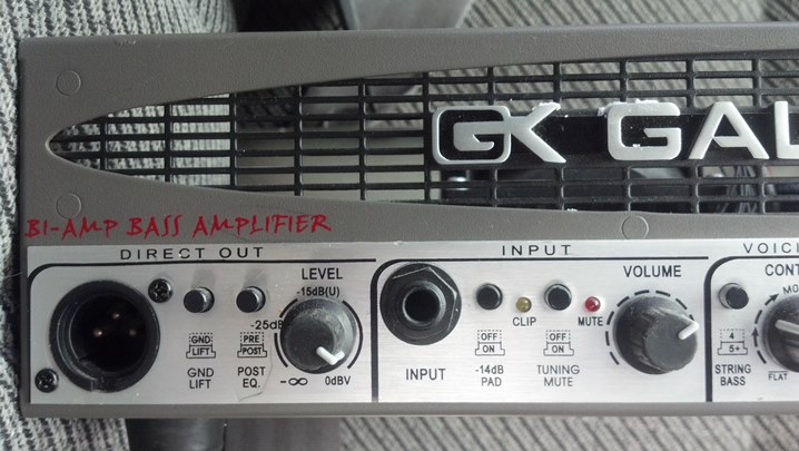
Let’s start off with some gratuitous tech porn.  This unit has a built-in DI box with a balanced output.

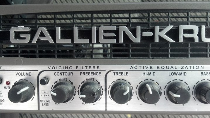
We have all sorts of tone-shaping capability.

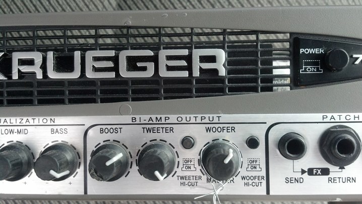
The separate outputs for tweeters and woofer are nice.

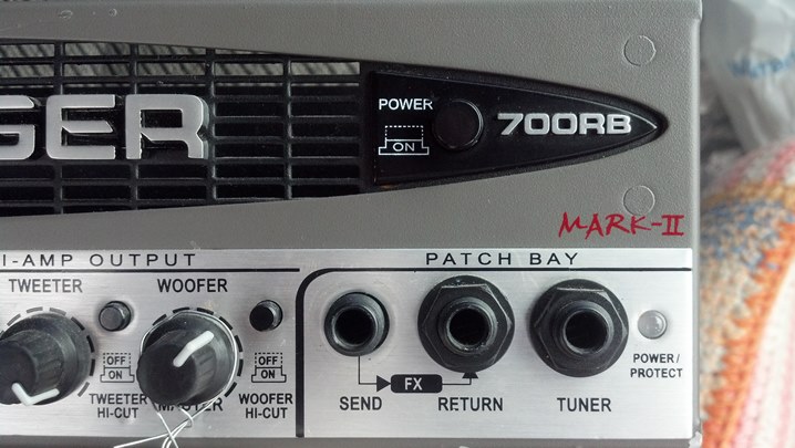
The effects loop connectors in are front, as well as an easy means to attach a tuning pedal.  The POWER / PROTECT LED is RED until everything stabilizes, then turns green;  And, of course, the ubiquitous ON/OFF switch.

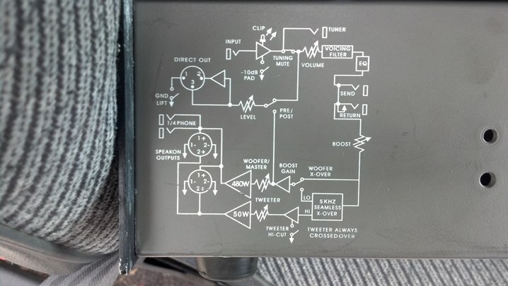
Here is a block diagram for those who are unfamiliar with all the architecture and features of this amp.

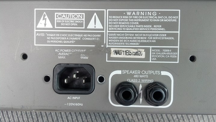
These speaker outputs connect the combined woofer and tweeter signals to a cabinet.  The AC input is self-explanatory.

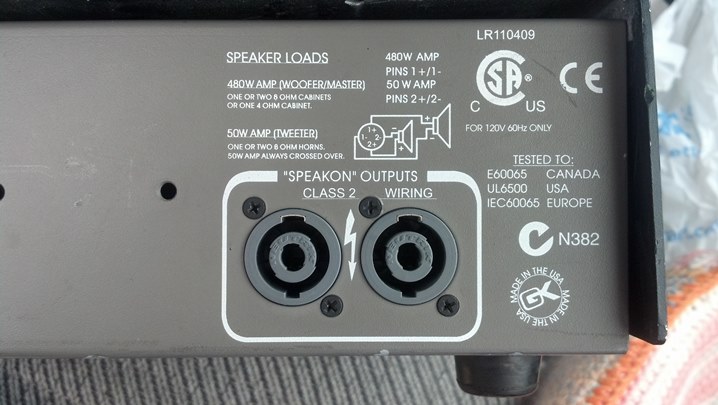
These Neutrik connectors allow access to the separate tweeter and woofer amps, if that works with your cabs.

The fuse was blown, but I smelled something burnt.  The main circuit board needed to come out.

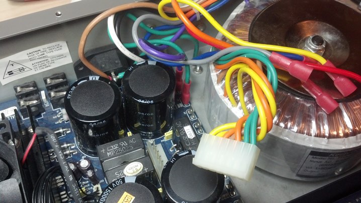
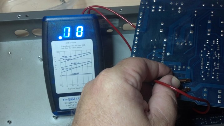
We had a blown fuse, so I did some troubleshooting before replacing the fuse and powering up again.  The filter capacitors were slightly swollen, so I checked them for ESR.

The ESR meter showed that these caps were OK.

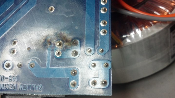
The only visual sign of anything burned was this residue from an arc flash. Little bits of metal are burned and blown around the vicinity of an electrical arc.  The electrical surge of the lightning transient plus the conductivity of the ‘smoke’ from the arc flash blew the fuse.  All this happened during the lightning strike.  Fortunately the circuit board was not pitted.

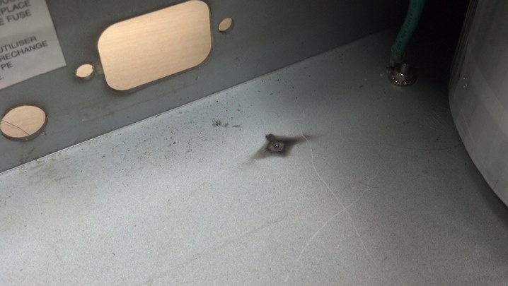
The case was pitted.  This is where the metal in the arc flash came from!  We’ll clean this up and then replace the fuse.

Everything worked well.  The unit was returned with a very modest repair bill.  We have yet another happy customer!

Thanks for reading all the way to the bottom!

Contact – David Latchaw  EE

cell – 281-636-8626

Crate CR2R Combo Refurbish

The oak cabinet houses a simple solid state amplifier and a Celestion G12 loudspeaker.  The rustic look is intriguing; the wife agreed that this matched the decor and would therefore be allowed into the house.  This particular amp was languishing in a pawn shop until Dave called me to bring the truck and refurb this guy at the Unbrokenstring Shop!

The grille, metal handle, and metal corners had plenty of surface rust.  The wood hadn’t been conditioned in, like, forever.  And, it didn’t play.  When shaken, loose parts were heard rattling around.  So we have a starting point for electrical test…

A scan of the front panel shows typical controls found on 1970s era units.  The LO input has a 10dB pad in series with the input jack.  The BRIGHT switch is a throw-back to earlier times.

This unit has a three-band EQ and a reverb tank.  As we will see later, the electronics were built by St. Louis Music.  Crate had licensed Ampeg’s intellectual property and were rebranding it into their own units.

Here’s a quick peek at the rear panel.

A pair of TO3 transistors handles the push-pull duties.  Nice to see insulators over the cases of the transistors, which may be at 40 volts or more with respect to ground when operating.

A foot switch can be plugged in here to enable or disable the reverb.  Don’t know if the LINE IN and LINE OUT signals are really ‘line level’ e.g. 2v or not, but back in the 1970s, who cared?

A utilitarian Celestion loudspeaker handles the electricity to sound transducer duties. This particular loudspeaker is in good shape considering that it is probably original for that time period.

I took this pic to preserve the location of the reverb tank wiring and the cable to the loudspeaker.  They are all RCA males.

The output from the reverb tank was manually marked with a Magic Marker. Interestingly, the Magic Marker ink has dispersed into the plastic jacket of the cable but is still visible.

I unscrewed the chassis and removed it out the back of the amp.  Yeah, we’re a little dirty and dusty.

Now we have a little more room to remove stuff to clean up the cabinet.  Two screws hold the reverb tank in place vertically along the side of one wall.

The grille is held in with some of these screws.  Everything is coming off in order to clean this cabinet and oil it.

The grille frame is pine, painted black.

Here we find Vincent Price’s “funk of forty thousand years.” TIP: If you don’t get the association, Google Michael Jackson “Thriller” lyrics.

This portion of today’s program is brought to you by Pledge furniture polish.  It contains enough petroleum solvents to clean the wood and condition the exposed wood in the scratches.

The bottom of the cabinet hasn’t been this clean since 1978.

Now, to start on the electronics. I took this pic to document the orientation of the BRIGHT slide switch.

Rather than unsolder these wires, I’ll remove the front panel jacks to liberate this side of the circuit board.

I’m going to disconnect this internal wiring to free the circuit boards.  This pic is for documentation purposes.

All the knobs pull off, no set screws.  These knobs have an interesting tri-lobed scheme to hold to the knurled shafts.

Removing the nuts will free this side of the circuit board.  This socket is covered in felt to keep from scratching the paint.

Remember this switch? The BRIGHT switch needs to be detached from the front panel.

Aha! Here’s one of the loose parts rattling around inside the cabinet. Only the component leads secured this part to the circuit board. Over the years, the leads were repeatedly bent by vibration, work-hardened, and eventually broke. No audio passes through a broken lead!  There are two of these guys running loose inside the amp.

The preamp board is loose from the chassis.  These controls will be cleaned and lubricated before reassembly.

Some service has been performed in the past.  Why can’t these people remove the old rosin solder flux?

More solder rework is apparent here.

The white stuff is RTV adhesive, commonly used to secure components in place so they don’t vibrate loose.  We have a problem here.  Can you see it?

More tech porn.  The topology of this preamp is pretty standard, with op amps performing the heavy sonic lifting.

Everything here looks pretty good.  Let’s fix what we’ve found so far.

This cap came unsoldered.  It checks OK otherwise so this will be reinstalled right where it is.

Remember those green parts that were found rattling around inside the chassis?  My fingers are pointing where they go.

Radio Shack had these parts in stock.  They are installed here.  This board is the power amp assembly.

The first amplifier IC right at the input is bad. It goes here, to the left of center of this picture.

My reassembly helper has decided to perform a Quality Audit.

The controls were cleaned with Blue Shower, then lubricated with Rid-Ox, sprayed directly into the control. The control shafts were twisted from one extreme to the other several times until the Rid-Ox evaporated.

The grille is firmly reattached to the cabinet. Loose grilles are often the source of mysterious buzzes and rattles.

This yellow gripper is handy as a screw starter.  The power amp board is being installed here.

And our old friend, the BRIGHT switch, is reattached here.

The reverb tank is refastened to the side wall here. The Pledge furniture polish does a good job of removing crud from the tank sleeve.

More reverb tank action.  Exciting, huh…

Those cables are finally put back where they belong.

This guy doesn’t look too bad now. This is just a straight-ahead practice amp, but the cool factor is bumped up because it’s a Real Crate. And it plays well!

Thanks for reading all the way to the bottom!

Contact – David Latchaw EE
cell – 281-636-8626