Noisy Volume Control in the Peavey XR-600B Mixer Amp

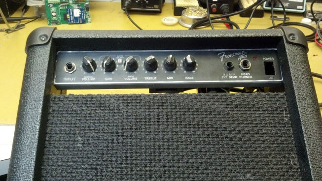
This honest, hard-working powered mixer lives in a music room, where all the musicians can plug in and hone their craft.  After all these years, the volume control has become dirty and intermittent.  The Unbroken String Crew realizes that this repair will be a wonderful opportunity to show an Old School method for repairing the part, not replacing it.

The unit is a wonderful example of intelligently-packaged, simple product that just works.  Four screws, and we’re into this unit.

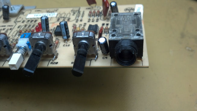
These two circuit boards carry all the front-panel controls and interconnects.

Most of the interior of this unit is empty space.  Plenty of room for the reverb pan and power transformer on the bottom.  The amplifier is seen on the far side, supported by the rear panel.

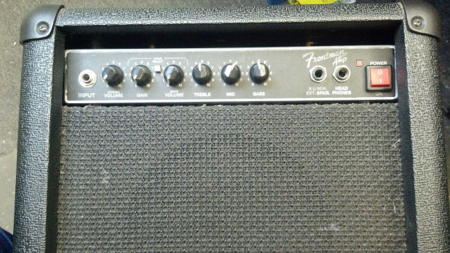
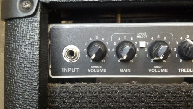
The objective today is to clean up the ‘MAIN’ pot, in the lower left hand corner of the big front panel.

The nuts on the front panel controls along with the nuts on the quarter-inch jacks hold the front panel together.

Everything is hand-tightened.  A socket and my hand allows enough torque to get the nuts loose.

Here’s what’s behind the front panel.  Now the real work begins!

I’ve desoldered the volume control.  What I intend to do is to rebuild this control, rather than replace it.  By rebuilding this control, we can preserve the original markings, some of which are useful when proving the age and authenticity of guitars and amplifiers.

I’m using a colorful rag to catch all the small parts that always seem to fly away.  First, we’re prying open four fingers that hold the back of the control on the body.  Yes, I know I shouldn’t use cutters as a pry…

The back of the control is on the left.  Inside the control we see the central shaft.  On this shaft is a rotor, which is the part that turns with the central shaft.  The actual resistor is the dark circle facing the rotor.

We’re looking at two pairs of sliding contacts.  The large pair on the left, towards my hand, run on a circular metal contact ring.  The overlapping sliding contacts to the right actually touch the resistor itself.  These sliding contacts must be clean and dry.

Do not attempt this at home!  Leave this to trained professionals!  Seriously, a pink eraser is a quick and effective abrasive tool for cutting the crud off the sliding contacts.  But we need to be super-careful here because these sliding contacts are very delicate.

The larger sliding contacts touch this circular metal contact ring.  The part that I’m holding in my hand is the actual center leg of the control that solders to the circuit board.  This ring has a lot of surface oxide and contamination, and is probably why this control was noisy and intermittent.

And here is the circular ring without surface oxide and contamination.  We have now begun our path back to a repaired control.

Moving our attention now to the resistor, we see that this ring is actually not too dirty.  However, this is very delicate, so we will go slow here and Do No Harm.

All I’m going to do here is lightly burnish the resistor and set it aside.  The cotton swab shows what came off the surface of the resistor.  I think we’re good here.

Plenty of lubricant remains in this unit.  Here, I’m wiping away the surface of the lubricant to remove dust and oxidation.  What is under the dust and oxidation is perfectly usable, and will be left in place.

The clean lubricant goes wherever there are moving parts EXCEPT on those sliding contact surfaces.  You will recognize that this passage is where the volume control shaft passes through the body of the control.

Everything goes back together where it belongs.  I’ll hold this together with one hand while I reach for the pliers.

The four fingers are crimped back into place.  This portion of the job is complete.

The control is soldered back into the board where it originally came from.  And, yes, my mama told me not to end my sentences in a preposition.

Everything lines back up, including the newly-resoldered control.  We’re about done here!

We’re back together.  The master volume works perfectly.  All the channel strips are good.  All Systems Go!


Thanks for reading all the way to the bottom.  I hope you have seen enough of the process to gather an understanding of what might be involved in repairing a control versus replacing it with a modern unit.  I discussed using vintage parts to repair my Gibson GA-30 amplifier, and made the decision on that project to use modern parts.  Likewise, in the previous post about tearing down the Shure 555H microphone, the switch was repaired instead of replaced.  So keep the repair process in mind when working on vintage gear that may be dated from EIA codes stamped on controls.  Gear may lose value when non-original parts are installed.


Contact Info – David Latchaw EE

281-636-8626

Marshall MG15CD Input Jack Fix

Someone had attempted to repair this little practice amp, and now it was still not fixed and there were parts missing to boot.  The Unbrokenstring Crew To The Rescue!

Finally, something that is not made in China!  I’ve worked in South Korea in loved it.  Wonderful people.

The input jack is supposed to be soldered to the circuit board, but the solder joints failed completely.

Strictly speaking, it’s poor practice to use electrical connections for mechanical attachments, but once we moved from point-to-point-wired amplifiers to circuit-board-centric amplifiers, jacks and potentiometers were suddenly used as mechanical mounting devices as well as electrical components.

So let’s start by removing all the old solder and cleaning out the holes.  You can see here that these are not plated through, which works in our favor.

The other half of the joint is the component leg.  Oops, these have failed in the mechanical aspect.

So let’s add our own new legs.  Prosthetic leads for input jacks?  Maybe someone will write a song about it…

We’re ready to go back into the circuit, with fresh copper leads which should work as well as the old component legs.

We need to be quick when soldering these new legs to the circuit board, or we’ll melt the work we’ve already done.

I think we’re ready to begin reassembly.  The circuit board is entirely supported by what you see here.

The screws that held the chassis to the top of the amp enclosure were missing.  We used some extra screws from the shop to replace the missing mounting screws.  New ‘Tinnerman’ nuts were located and pressed into service.  I think this is going to work!

I think Erika is happy with her repaired amplifier!


Thanks for reading all the way to the bottom.

David Latchaw  EE

281-636-8626

Fender Frontman Bullet Amp QuickFix


01ThePatient

The problems with which this amp suffers are the Bread and Butter for electronic service guys.  Broken power switches and broken input jacks are common in so much gear these days.  Let’s get to work!

02OrigPwrSwThe original power switch was just “plum wore out.”  This was a mechanical problem, not so much an electrical problem.  The contacts were intermittent due to metal fatigue of the components inside the switch and the decay of the plastic used to manufacture the switch.  Out it goes!

03BustedInputJack

The plastic body of the input jack was shredded as well, a victim of time and use.  Funny thing is, Fender continues to use this style of plastic bodied jack on their higher-end amps, which I have considered to be a real weakness, particularly to anyone who uses their gear to earn a living.

04InputJackRemoved

My strategy was to replace the plastic input jack with a steel Switchcraft unit that bolted to the front panel, then wire from the terminals on the jack to the proper circuit board pads.  Here I have marked which PCB terminals were tip (T) and ring (R).

05PCB

The rest of the circuit board was in good shape, with no signs of damage.  The hybrid output amp module (barely visible at the top of the picture) had already been replaced and was still operational.

06Screw1

But I’m sure that you sharp-eyed readers discovered that the Fender chassis was NOT mounted in a Fender enclosure.  Someone in the past had re-purposed an Epiphone enclosure and loudspeaker for service with the Bullet amp.  In the process of melding the two together, they got creative with the mounting hardware.  Yes, that’s a wood screw jammed into the threaded bushing on the Bullet chassis, and bent over to hold it in place.

07Screw2

Just a little higher on the hardware evolutionary scale is this sheet metal nut, jammed over another wood screw.  This was all coming out if my fingerprints were to be found on this thing!

08CordStrain

The original line cord would be re-used with the new switch.  Here, I have contrived a strain relief scheme involving a black wire tie and a wire clamp, securely bolted to the chassis.

Anyone who would pull on this would be able to pick up the amp and swing it around, although with a little practice amp like this, swinging it around would not be hard (but could be hard on the furniture.)

09NewACsw

This is a closeup of the new power switch.  The body of the switch was round, so the edges of the rectangular power switch hole in the front panel were enlarged slightly with a file so that the new switch fit properly.  As you will see in a moment, the front bezel of the switch was rectangular, which covered the original hole nicely.

10NewACsw

Not a bad job on the power switch, I’d say!

11Screws

Some machine screws were secured that were the proper length and thread size.  Here I’m bolting the chassis securely into the top of the enclosure.

12BackTogether

Everything is back together.  On the right end of the panel, you can see the new Switchcraft steel input jack.  It is wired directly to the chassis with short pieces of hookup wire.  This jack will probably outlast the rest of the amp.

13FrontView

This is a front view, showing the difference between the steel input jack (on the left) and the factory Fender plastic jacks on the right, next to the power switch.  By the way, the external speaker jack was also broken, but the owner did not need to use that feature so we left it as-is.

14WeAreOn

We are ON.  The red LED was smashed back inside the amp, so part of the reassembly process was to secure it back in its hole in the front panel.

15JackLooksNice

The customer was very pleased with the input jack.  The amp works 100%, much to his parents’ chagrin.  Rock n’ Roll!