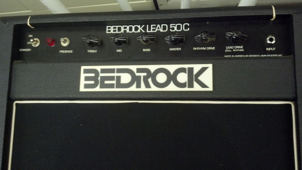
My father found this amp in a pawn shop in Enid, Oklahoma around 1969. A high school buddy and I had a guitar duet act, and to support us, he was renting Kustom amplifiers to use as PA systems for our gigs. I think my father purchased this amp as a way to cut his rental expenses. The amp worked, and it served me well throughout my high school years. Unfortunately, I knew nothing of its background and really didn’t appreciate the bit of guitar history it represented until I pulled it out of the closet last year to try it out again.
Before my father purchased this amp, someone had removed the smaller loudspeaker and replaced the larger Jensen loudspeaker with a similar Utah unit, and had changed the output transformer. Perhaps we can update the amp, get it working, and return it to a configuration similar to the way it was Back In The Good Old Days. Well, let’s get to work!
 The leather handle was not original. This item was sold as a repair handle for luggage. And now it too was broken.

This bracket used to have a center post that passed through a slot in the original leather handle. The original rivets were weak and were easily removed from the amplifier cabinet. As a replacement, I ordered a Fender amp handle and hardware (yeah, call me blasphemous, but the flat Fender leather strap is probably closer to what originally shipped on this cabinet than anything you have mounted on your relic Gibson amp.)
 I removed the amplifier’s chassis and put it on the bench. We’ll get back to this in a moment.
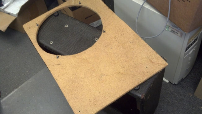 The cabinet was disassembled as well. The old baffle was crudely cut from half-inch-thick particleboard to mount the single Utah loudspeaker. Just after this picture was taken, it crumbled into several pieces and discarded, a victim of age and humidity. A new one would be fabricated from baltic birch plywood to accommodate the second smaller loudspeaker, as an acknowledgement of the original configuration of this amplifier.
 Thanks to eBay, I found the eight inch loudspeaker to match the larger twelve-inch loudspeaker already installed in the amp. I just love NOS (New Old Stuff!) I had agonized over re-using the big Utah loudspeaker or moving back to the Jensen loudspeakers, but the agony was soon ended when I balanced the checkbook. These Utah loudspeakers will be fine for now, as I really wanted this amp as a daily player and not a museum piece.
 I sketched out the location of the loudspeakers with respect to each other and with respect to the amp enclosure on the piece of baltic birch plywood. Here you can see the starting holes from which the orbital jigsaw will start through the plywood. I do have the router and the circle template, but I opted for the jigsaw to keep the mess to a minimum as bad weather kept this work inside the office.
 One down!
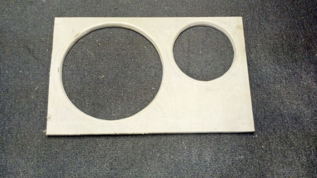 Both loudspeaker holes done and rounded over to minimize edge diffraction. The plywood was also trimmed to fit in the amplifier cabinet.
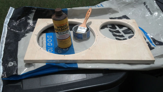 I applied several coats of wood hardener. This stuff soaks into the wood, sealing and strengthening it. The resulting baffle is as rigid and stiff as I can possibly make it. Note – try this wood hardener treatment on old guitar amp cabinets that have become ‘weak’ over time. You might be pleased with the improvement. The baffle was then painted with a semi-flat black paint on the front side.
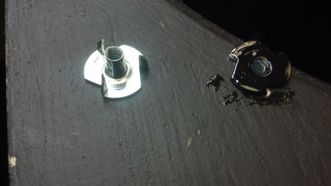 The loudspeakers themselves would be bolted to the baffle using these tee nuts, which were also painted black so that they would not be visible through the grille cloth.
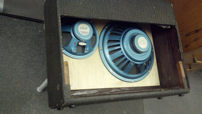 Here’s the cabinet so far. Loudspeakers are bolted to the baffle, and the baffle is bolted to the original amplifier cabinet. Only the front (grille) side of the baffle is painted black; you are looking at the sealed but unpainted side.
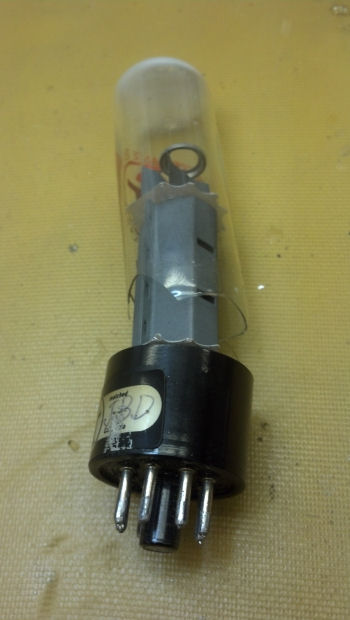
 The chassis was obviously dirty. Note the clouded tube. This is an indication that the glass envelope of the tube has been compromised and moisture has ‘gotten’ the ‘getter,’ the region at the top of the tube that is usually silver in appearance. We will pull the tubes and check them, but I don’t have really high hopes that we will find many good tubes here.
 Here I’ve cleaned the painted chassis with leather cleaner and conditioner, the same stuff that you would use on work boots. It not only cleans well, but does a good job of preserving and restoring the brown paint with which the chassis was painted. Good stuff!
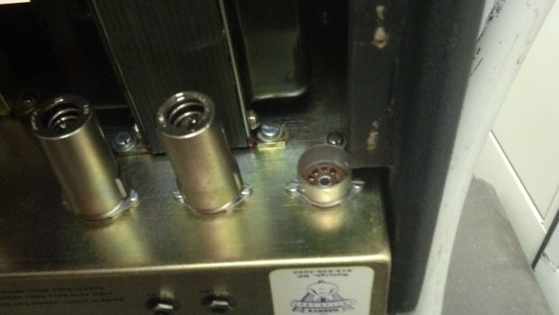
 The top of the chassis is squared away using the leather cleaner. Oh, and all the tubes were trash. But checking the tube layout against the schematics available from Gibson, I discover that this was probably an ‘interim’ model, between the GA-25 and the GA-30. The circuitry is the GA-25 circuit, built with discrete triodes for the phase splitter, and using the four-input circuit of the GA-30 amplifier on a chassis marked GA-30, That information places the date of manufacture of this amplifier chassis around 1949, Fresh NOS tubes are on order from my vendor.
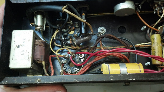 Flipping the chassis over, we see the power supply choke on the left side of the chassis. One of the output tube sockets is nearest the observer, and the high voltage caps is the yellow units visible to the right of the picture. The high-pot test on the choke shows that it’s good to over 400 volts.
 Shifting our gaze to the middle of the chassis, we see some of the black capacitors which are interstage coupling capacitors.
 Moving to the right, we see the other high voltage filter capacitor and the rest of the interstage coupling caps. These will all be changed out with modern components. As I mentioned earlier, I wanted this amp as a player, not a museum piece. Some collectors will retain the appearance of their chassis by reusing the package of the original component. The wax and internal structure of the capacitor would be removed, a modern component placed inside the package, and the ends resealed with the original wax. Maybe this is important to some people, but this amp has already been worked on, and I want it to play it, not look at it.
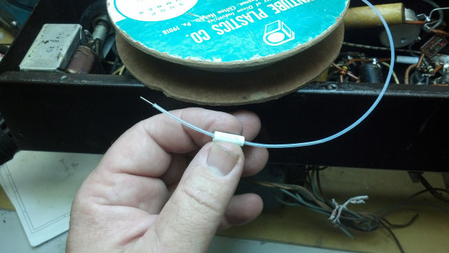 Here I am covering the component lead of this new interstage coupling capacitor with Teflon tubing. If this style of construction is good enough for America’s Space Program, it’s good enough for me.
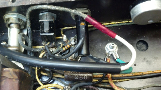
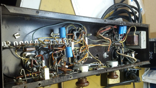 The blue electrolytic capacitors are the new high voltage filter caps, and the small white cylinders are the new interstage coupling capacitors. At the top if the picture, you can see a gray wire leading away from the terminal strip towards the center of the chassis. This carries a sample of the output signal back to the preamplifier tubes, implementing a form of negative feedback to the amplifier. This appears to be an aftermarket modification. I left the circuitry in place but left the option to remove the sample tap at the loudspeaker if I don’t like the sound of the negative feedback added to the circuit. This is a guitar amplifier, not a hi-fi.
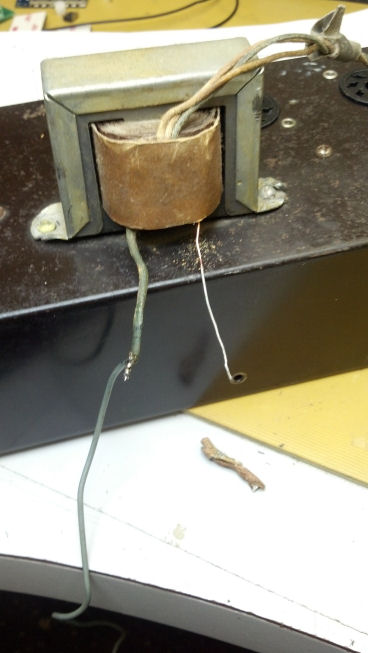 The insulation on the output transformer crumbled. This has been worked-on before, and I don’t have the ‘correct’ cotton sleeving used on old electronics like this… nor do I wish to use it here.
 New PVC insulation was slipped over the lead of the output transformer and more wire was soldered to the output transformer lead, Heat shrink tubing is employed to protect everything. The black thing on the right side of the pic is the nozzle of my hot air rework pencil, perfect for shrinking tubing.
 This is the first power check. Only the rectifier tube has been installed. The voltages for filaments, high voltage, and bias points all check OK.
 The input circuit is now driving the phase splitter tubes, but the final amplifier tubes are omitted for testing. This allows everything to be checked at ‘no-power’ levels but with realistic loads on the power supplies.
 One issue I found was that the slide switch labelled “Tone Expander” was dirty and intermittent. This switch was disassembled, cleaned, and reassembled. Not a job for the faint of heart.
 The power cord was in excellent shape, which meant I probably replaced it back in the 1960s and forgot about it. When I rebuilt the amp, I thought that it was low-risk to leave the two-wire cord in place as there were no ‘death caps’ across the AC line as are found in some Fender amps. However, the chassis was ungrounded except through the metal parts of the electric guitar and thus hum appeared.
 So I installed the meanest, nasty-est, biggest, baddest three-wire cord set that I could find in place of the original line cord.
 Now that the shape of the plug established which conductor was hot and which one was neutral, I changed the wiring so that the fuse holder and ON/OFF switch was now in series with the hot (black) wire in the power cord. The green wire safety ground got its own lug at the star grounding point seen in this picture.
 One final test before final assembly. A microphone is used to check for hum and low-level signals. Later, a signal generator will replace the microphone and a resistive load will be used in place of the loudspeakers to verify that the output transformer is up to the job of driving four ohms. Output tube operating point will be verified. We are not far from Rock-n-Roll Land now!
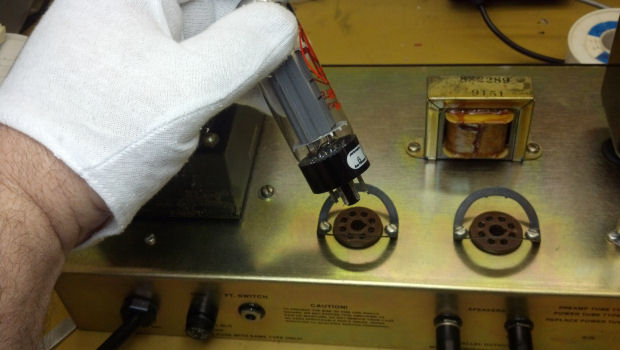
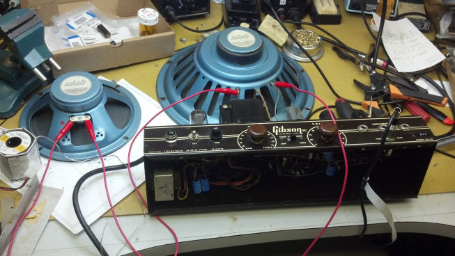
 The loudspeakers and chassis are placed in the guitar amplifier cabinet. The output transformer interferes with the frame of the larger loudspeaker, so it was moved to a place of honor on the baffle. Some sane and rational wire dress keeps things under control, or at least that’s the plan.
 Here are all the tubes. All that remains is to reinstall the back panel and final checkout. This is one of my favorite pictures.
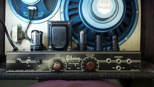
 Go Time!

 Mark’s like-new Vox AC30 worked well, except nothing came through the reverb signal path. The foot switch checked out, so we loaded it up and worked on it at the Unbroken String lab.
 A gorgeous amp, built like a tank, sounds sweet, but no reverb. Slapping the tank didn’t bring forth any spring sound, so it’s time to get it on the bench for some minor surgery and some amp tech porn pics!
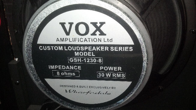 Some amp tech porn. Wharfedale supplied loudspeakers for AC30s for one year, Sure enough, here they are!
 The chassis slides out of the back of the amplifier. Time to check the preamp tubes, seen mounted horizontally behind the final amp tubes in the foreground.
 Well, that was easy to find. The current through this tube barely moved the needle.
 Comparing the bad tube to its neighbor, the getter material is a little darker. Nothing else out of the ordinary here.
 Thankfully, economic sanctions against the Russians haven’t pinched off the free flow of SovTek 12AX7 tubes. Yet.
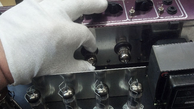 Some techs cuss at the rubber shock mounts around the tubes as you see here because they interfere with inserting the tube into the socket. But the tube gods smiled this afternoon.
 We are ON but nothing is coming through the reverb circuit. Again. Uh oh. Have I failed?
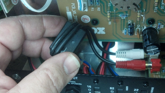 A visual check sometimes yields the quickest results. Nothing was out of the ordinary. But this clamp-on ferrite choke does not appear on the schematic. The red and white RCA cables go to and from the reverb tank. What’s going on here?
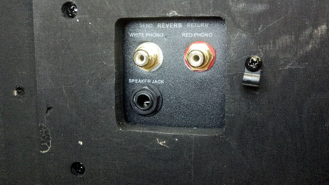 The other end of those red and white cables terminate in the bottom panel of the amplifier cabinet. The cables from the reverb tank plug in here. The signal passes through the amplifier cabinet through these bulkhead RCA connectors. Interestingly, the loudspeaker wiring goes through this quarter-inch jack, greatly simplifying service. Thank You VOX!
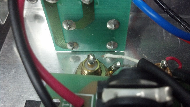 This is a view from the other side of the black panel in the previous picture. This open white wire goes to the RCA plugs that actually plug into the amplifier circuit. Now we’re onto something!
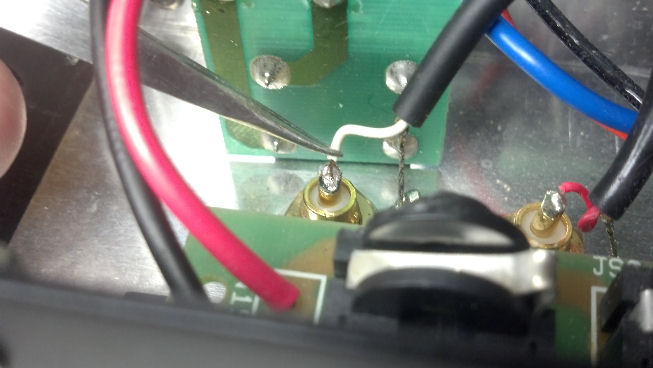 Space is cramped, so I took some time to set up this portion of today’s program. I removed some solder from the RCA bulkhead connector, so I can make a new solder joint. I’m using a pair of tweezers to get the wire lined up because my big fat fingers won’t go inside the amp here. And I don’t want to be anywhere near the hot soldering iron when I’m fixing this.
 Ah, that’s much better. The original Chinese solder was that high-melting-point lead-free stuff, containing lots of tin. In my experience, the lead-free solder is a bit brittle, so this particular solder joint was at-risk since the day it came from the factory.
 While I’m on a rant about lead-free solder, let me rant about this ferrite choke. This part has nothing to do with sound reproduction or tone, but was likely added in an effort to comply with FCC or UL regulations. The only support for this choke was the wires from which it was dangling, and you saw the damage it caused. Here, I’m using a tie strap to hold the ferrite choke away from anything delicate.
 While I’m at it, I’ll add a second tie strap. That should keep this from happening again.
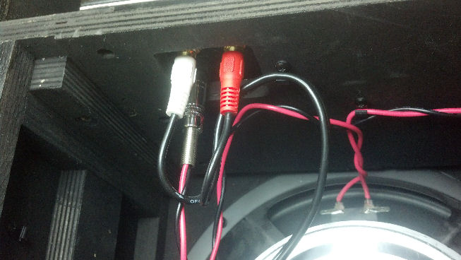 Now everything is hooked up again and the reverb tank really, well, reverbs! I think we’ve got it fixed now. This is a nice shot of how the signal path moves from one section of the amp enclosure to another.
 I had forgotten how many screws had been removed to take this guy apart.
 Here’s more screws. Are we there yet?
 Mark has his amp back and he is pleased! He mentioned that this amp is for sale, so if you are interested in this unit, drop me a message from the “Contact” page and I’ll hook you up.