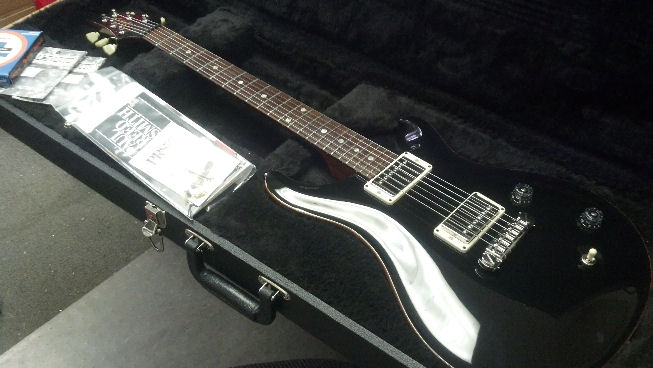
This lovely all-black (murdered) Mexican Strat is another one of Dr. Shoen’s axes.
This guitar had languished in the trunk of a car and had acquired an interesting twist in the neck. A very fine white dust permeated every internal cavity of the guitar. The tremolo was functional but for some reason, releasing the tremolo did not necessarily return the tuning of the open strings to where one would expect it to be. A few of the bridge adjustment set screws were corroded beyond usefulness.
A conventional setup was just not adequate to return this guitar to playability. More work was needed. This is something that happens from time to time… a situation that every guitar tech dreads. However, I run where angels fear to tread!
Let’s press onward to disassemble this guitar, do a little exploratory surgery, and take some guitar tech porn pictures along the way!
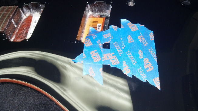
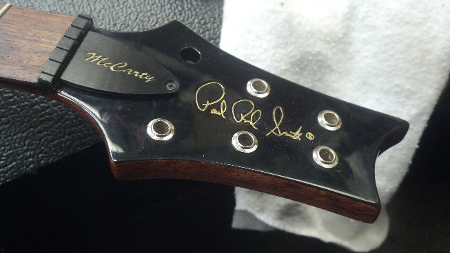
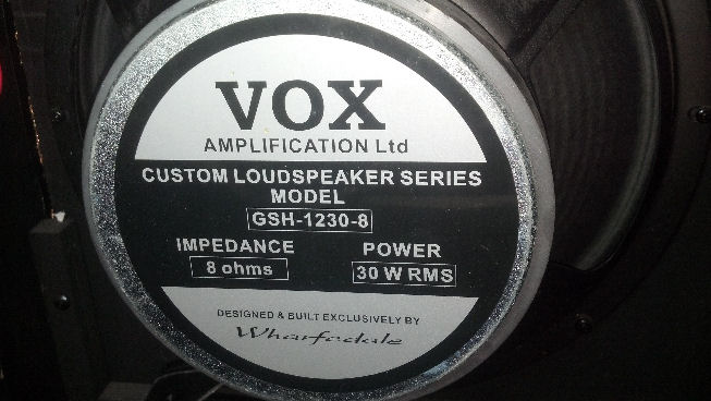
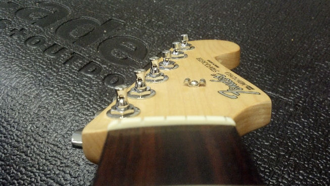
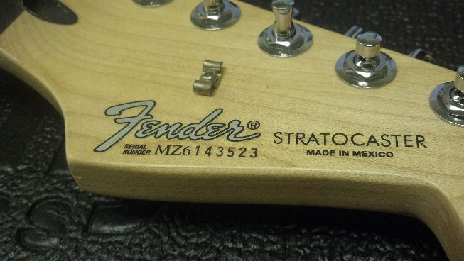 Here’s all the info you need to make illegal copies of this guitar, complete with a valid serial number.
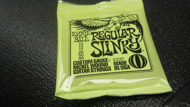 These are Dr. Shoen’s preferred string set. When I asked him why he puts these strings, he said that they are the cheapest. Excuse me while I scratch my head.
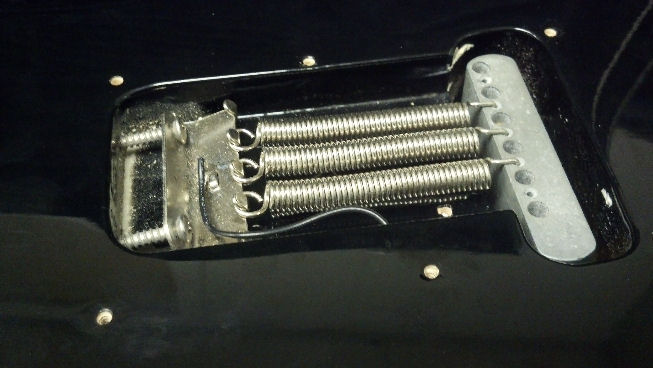
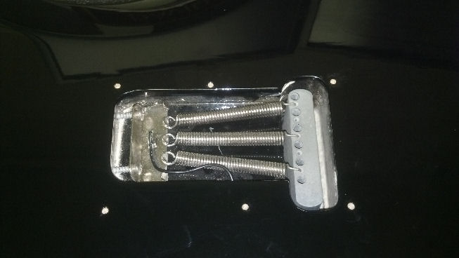 Can you see the fine white dust in the left end of the tremolo spring cavity? Another OCD peeve of mine is tremolo springs installed this way. Somehow it makes sense to some people, but the center spring will go slack before the outside springs. For a constant spring rate, the springs need to be parallel.
 Off they come. I feel better already!
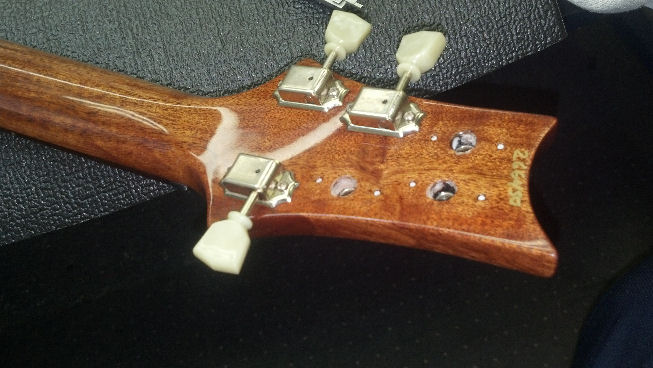
 Guitar Tech Porn. Nice locking tuners on the headstock of this Strat.
 Off comes the neck. No shims? The geometry of this guitar will change as we rework the neck twist and retrofit the bridge with new set screws, so I’ll go with this configuration and add shims later if we need it.
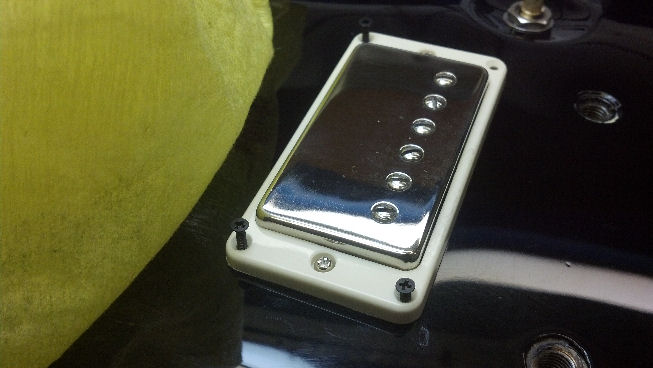
 These screws are really loose, almost falling-out loose, particularly on the treble side. Perhaps this has something to do with the tremolo not returning to an in-tune condition.
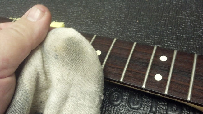 This fretboard was cleaned and oiled in the first setup. The guitar had not been played much since then. I suspect that the oil has floated out some more grime from the pores of the rosewood.
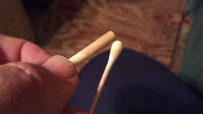
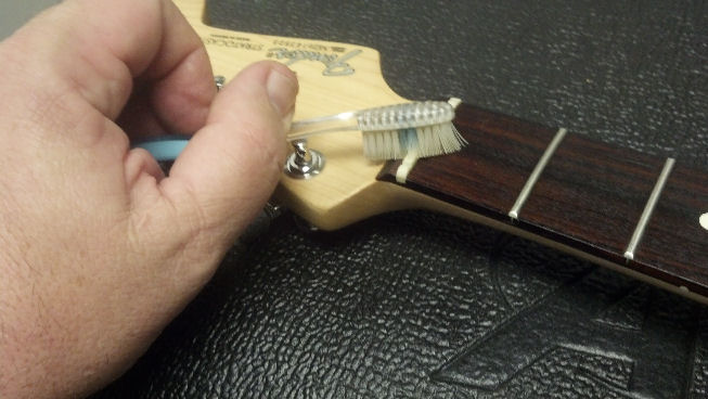 Some grime was softened around the nut, so I will apply this super-secret cleaning tool to the nut.
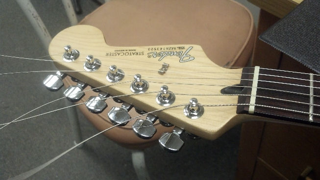
 Guitar Tech Porn. Lockers are unlocked, string holes are lined up, and there is a slight reflection of the nut in the surface of the rosewood fret board. Nice, wouldn’t you say?
 I began to disassemble the bridge and prepare to install new set screws.
 The new set screws are wrapped in Teflon tape, then threaded in from the bottom, where the Teflon will gently lock the screw in place while permitting adjustments in the future.
 The bridge is ready to return to service. Those tiny scratches are from the ends of the old set screws.
 Guitar Tech Porn. This is a side view from the low E string side, showing everything going back together.
 Guitar Tech Porn. Another view of the new set screws.
 The bridge has been reassembled. Before the strings are installed, I’ll tighten the intonation screws so that the saddles slide forward onto the open string as the intonation is set. I’ve discovered that if I start with the intonation screws fully extended, as they are here, tightening the screws results in string deformation as it rides over the saddle, and takes forever for the string to settle back into a ‘straight line.’ While the string is straightening out, there is no point in doing any further adjustments. Waste of time. So now I ‘subtract’ unsupported string length by moving the saddle forward to set intonation. The vibrating portion of the string is always ‘clean.’ Or I’m just OCD. Again.
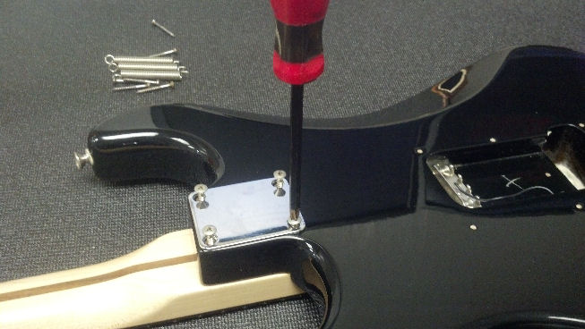 The neck goes back on without a shim, so we can see where we are with the other adjustments.
 Guitar Tech Porn. Slip the strings into the locks and tighten them down. Love it!
 The saddle should ride flat on the guitar body. It takes a while to get the screw heads in just the right place for this saddle to stay put. I’m a little worried that it won’t stay put when the string tension takes over. We shall see!
 This is the way an OCD Guitar Tech installs tremolo springs. It is also OK to put the two springs on the outside and have one in the middle. For now, this will work OK. I’m also thinking that those screws holding the bridge in place aren’t going to stay put, so this just seemed like the safest thing to do.
 Jen works the Strat into a lather. Sure enough, the tremolo is acting up again and the low E string is buzzing. Again.
 The tuning pedal shows that the tuning continues to change as she plays the guitar. Not good!
 Time to pull out the big guns. Callaham Guitars has a premium tremolo assembly for Mexican Strats. There are a couple of key differences that will help this guitar out, as we will see below. The strings and neck come off the guitar again at this point.
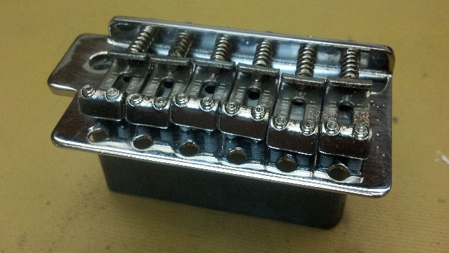
 A thing of beauty, the Callaham bridge is visually very close to the original Fender part, except for the CG stamp on the saddles. Referring to the earlier picture of the intonation screws, here I’ve got the saddles pulled all the way to the back so that the springs are compressed. As intonation is set, the vibrating portion of the string will get shorter.
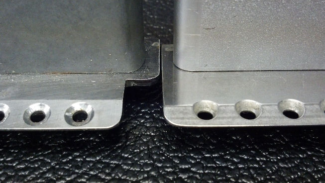 Here’s the real difference. On the left is the original Fender bridge, and on the right is the Callaham bridge. Note that the bevel does not extend all the way underneath the screws. This should allow the screws to be tensioned adequately to hold the bridge plate down, yet allow the tremolo to pivot the whole assembly on a single axis. In other words, the axis of rotation of the bridge assembly is held in a more stable point, right at the ridge of the steel, right underneath the screws. In the Fender system, we lose control of the geometry of the bridge once the bridge plate tilts, as there is no groove or knife edge anywhere on the screws to act as a specific pivot point.
 Another big issue with bridge stability is that the screw holes on the treble-side strings are stripped. The wood used to make this guitar body is a little softer than I expected, maybe alder. (You Strat-heads can message me with your inputs on this subject.) My plan is to cut plugs from rock maple, drill these six holes to fit the hardwood plugs, then re-drill the hardwood plugs to fit the Callaham bridge. I’m not a big Tone Freak but I have a feeling that the “Q” or the mechanical resonance of the body will be a little higher with the bridge screws held in place with rock maple. Maybe Les Paul was on to something when he laminated maple over mahogany.
 The plugs were cut using the 3/16th plug cutter from Stewart-McDonald. This 3/16th inch plug cutter makes the smallest practical sized plug available, to my knowledge. The smallest plug cutter I could find otherwise made a plug that was 6mm in diameter. Here is one of the rock maple plugs getting a coat of hot hide glue. The plugs are a little longer than the holes in the body, so I have something to hold on to!
 The inside of each hole gets a coat of hot hide glue, too. It takes about a minute to get each plug into the body of the guitar, at which point the hide glue begins to harden.
 Each plug is carefully trimmed flush with the original body contour. This takes a while.
 The new Callaham bridge is positioned at the point where the intonation adjustment will do the most good, then is held in place with some No-Mar tape. A brad-pointed drill bit is used to mark the center of each screw hole.
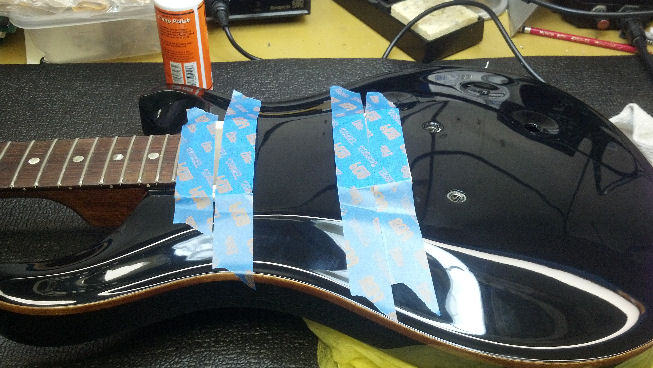
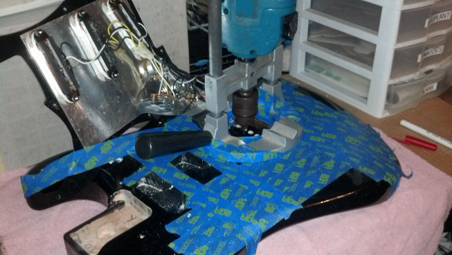
 This body is just wide enough to prevent me from using the drill press. Everything is taped off so I can use the hand-held Port-A-Lign to drill the screw holes accurately.
 The Port-A-Lign is doing its magic. The rock maple plugs go all the way through the body, but the screw hole depth is limited to the exact screw length by controlling the length of drill bit extending beyond the jaws of the Jacobs chuck. This allows the longest possible contact between the screw and the rock maple, all the way to the tip of the screw. A tiny bit of tape covers the ends of the chuck jaws, in case I hit the rock maple with the Jacobs chuck.
 Guitar Tech porn. The Callaham bridge kit even contained new screws.
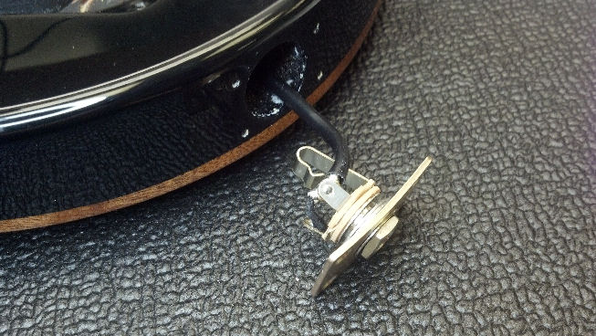
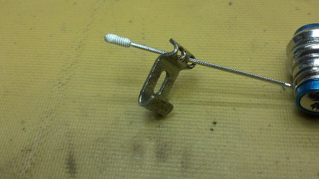
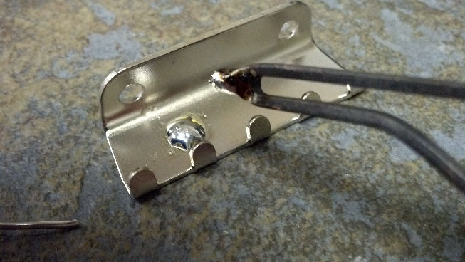 The Callaham tremolo spring claw was not tinned to accept a ground wire. No problem. I have a big soldering iron. The claw rests on a piece of ceramic tile because it gets WAY too hot to sit anywhere else while I’m doing this.
 The new Callaham tremolo arm is at the top, and the original Fender arm is on the bottom. Dr. Shoen prefers the longer arm. They are mechanically interchangeable, in any case.
 I got ‘medieval’ with the neck to get the twist out of it. No pictures, because it wasn’t pretty, and both my hands were busy.
After the strings were re-installed and the setup begun, I really didn’t need any shims in the neck. String buzzing was gone. The new bridge made it easy to radius the strings and set string height. Intonation was dead-on for where I placed the new bridge, with little adjustment necessary. Four tremolo springs were installed to get the tremolo working perfectly. I picked up this guitar to play it and didn’t put it down for forty-five minutes. It was alive in my arms. And I hadn’t plugged it into an amplifier yet. The sustain of each string was fantastic.
Dr. Shoen played it acoustically, with a lost look on his face. I was afraid something wasn’t right.
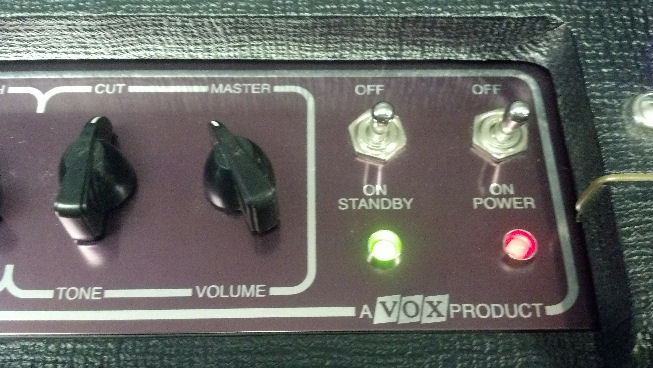
When he looked up, he said that he was ‘inspired’ by playing this guitar. He felt that I took a $500 guitar and turned it into a $1000 guitar. Jacked into my Gibson amp, this thing just sang.
Now go out and get that guitar out of the trunk of your car,
Thanks for reading all the way to the bottom!
CONTACT INFORMATION – David Latchaw 281-636-8626

 Steve really liked this pedal and gigged with it constantly. However, one day, he found that he couldn’t control it through the stomp buttons. The screen lit up, but nothing could be configured in the screen, and the pedal was useless. The Unbrokenstring Crew rides to the rescue!
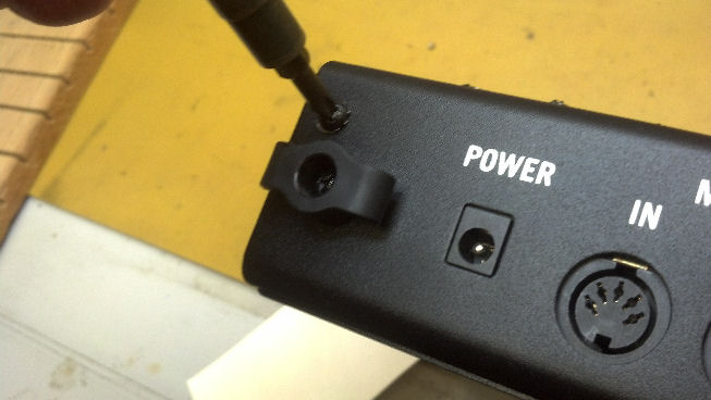 Yogi Berra said “You can observe a lot just by watching.” Sometimes, a little exploratory surgery will make the problem more apparent than going through the electronic menus. We’re going in!
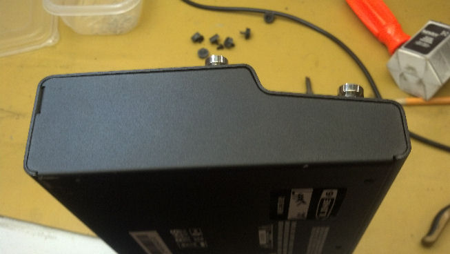
 It’s a little tricky to get the halves apart, but a little patience and good lighting lets you disassemble the unit.
 If you design your own circuit boards, as I do, you can order your circuit boards with any color solder masks. I see that Line6 used red. I’m good with that. Although I use red solder masks with prototypes, and green for production.
 The top row of stomp box buttons are fastened to the large circuit board at the top, with the DSP engine right in the middle. The lower circuit board handles the bottom four stomp box buttons. What do we have here?
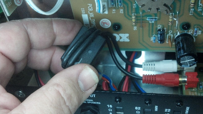
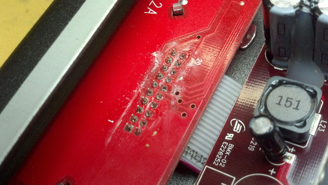 Nothing like a little spilled beer to brand this pedal as a gigging, mud/blood/beer-stained Texas Rock and Roll weapon. But the beer is not the problem.
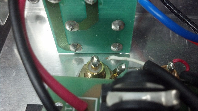
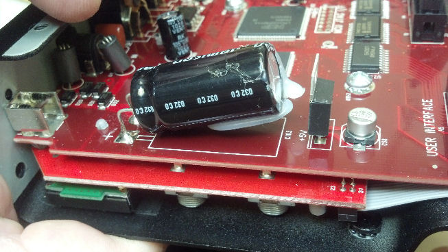 Nor is this the problem. But it points us in the right direction. Hot glue is commonly used in electronics, for encapsulation and adhesion. Here, a blob of hot glue kept this cap down on the circuit board. Or it should.
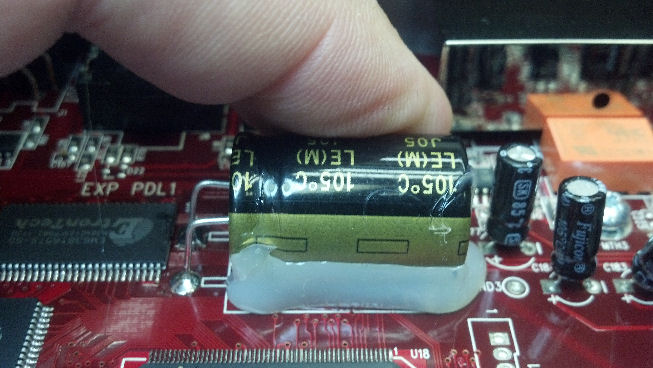 Here’s another big capacitor held down with hot glue. Any guesses yet why this pedal failed?
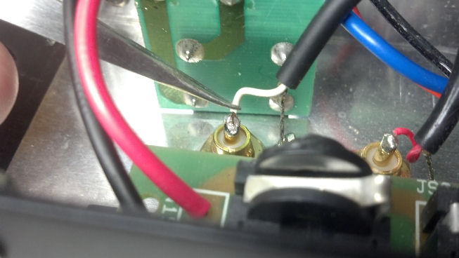
 I’m using the hot air rework soldering iron to soften the hot glue and stick down the big caps.
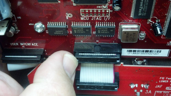
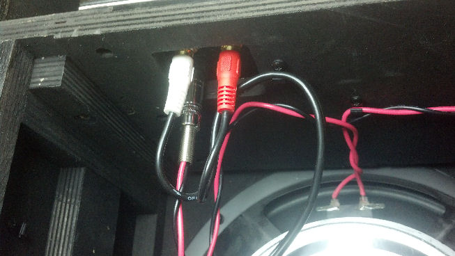
 The unit is reassembled and checks out fine! The firmware in this unit is update-able through the MIDI port, so if you need to update an older unit, you will need to connect this unit into the MIDI chain on your PC or laptop as there is no USB configuration capability. But the factory reset can be done through the menu, and is well-documented on the Line6 Web site.