Fender Princeton Chorus Input Jacks

01 The Patient

This solid-state Fender Princeton Chorus is an awesome little amp, but the input jacks were worn out.  A call came into the Galactic Headquarters of Unbrokenstring.  Could we help?  Yes we can!

02 Rear Panel Text
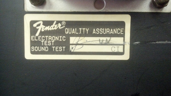
This unit was actually made in the USA, and the city of Los Angeles has duplicated the work of UL/CSA, for a fee, of course.  Is this a great country or what?  Let’s get to work!

03 Reverb Tank

I took a picture to document where the RCA plugs on the spring reverb tank belonged when it came time to reassemble the unit.  My memory isn’t what it used to be.

04 QC Sticker

Nice to see that someone cared at one time.

05 Loudspeakers
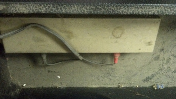
Separate cable pairs come out of the chassis for each loudspeaker.  Nobody has touched this in a while!

06 Broken Input Jacks
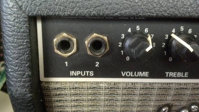
Today’s mission objective is to fix this.  You can read my earlier rants about plastic input jacks and international safety approvals.  But, to keep this amp original, we will go back with the authentic Fender part.

07 Chassis on the Bench01
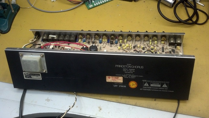
Here’s the amp on the bench.  WARNING: Tech Porn To Follow

09 Chassis Interior
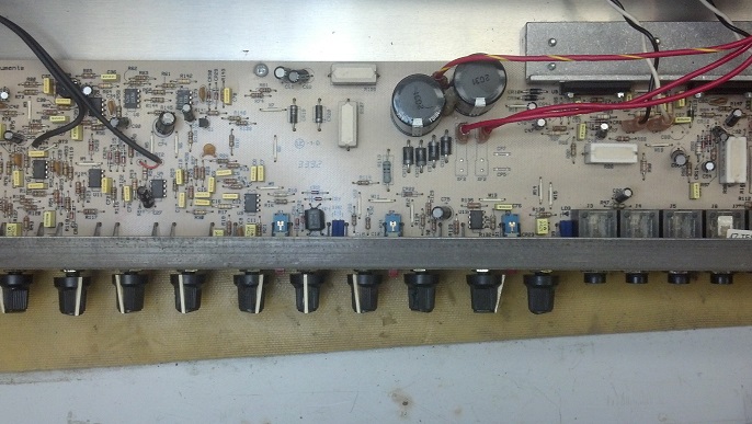
This top view shows the usual single-sided circuit board found in a lot of consumer gear.  This amp is pretty clean inside!

12 Knobs

Get your knobs off.

10 Felt on Socket
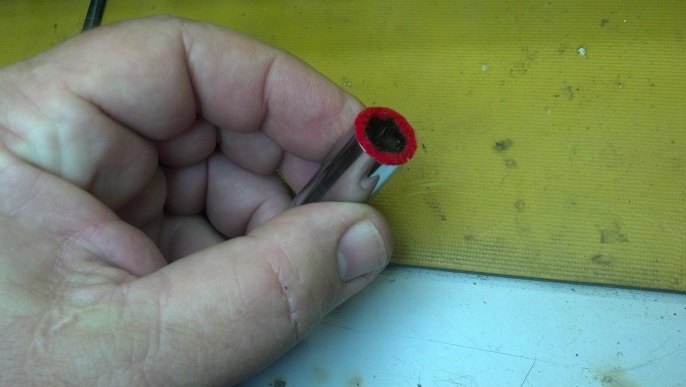
Some folks have asked about the felt-covered sockets I use.  Here is a closer picture of the one I will use on this faceplate.  The faces of a set of sockets is ground flat on a bench grinder.  A square scrap of felt from the fabric department is super-glued to the ground face.  When the glue is dry, an Exacto knife liberates any felt that is not glued to the socket itself.

11 Control Nuts Coming OffA little automation goes a long way.  This little low-rpm driver keeps the carpal tunnel problems away.

13 Closeup of Broken JackCompare the old jack on the left with the new jack on the right.

14 Another Happy CustomerThe reassembly is the reverse of the assembly.  Another happy customer picks up his amp!

Thanks for reading all the way to the bottom!

CONTACT INFORMATION:

David Latchaw EE

281-636-8626

Acoustic B100 Bass Head Rescue

Acoustic is a brand name owned by a national guitar retailer chain.  As far as I can tell, they are build in China and very few spare parts are available here in the United States.  This bass head was pulled out of a damaged cabinet.  The national retailer wouldn’t honor the warranty.  The ChiComs just want to sell stuff, not support it.  Can the Unbroken String Crew strike a blow for Truth, Justice, and the American Way?

Rather than use an attenuator switch, the user selects an input appropriate for his/her instrument and plugs in here.

Some bass amps separate the gain and volume knob.  I really like this setup.  The notch is handy for feedback control.

The split mid-frequency EQ is an interesting option, although (spoiler alert!) once I got this amp running and it worked well, I really didn’t get a lot of benefit from this.  Maybe you five and six string bass people can weigh in on this feature.

The big blue pilot light was visually interesting and bright.  I can’t say it went well with the paint scheme, though.

No audio came through the amp.  A quick inspection and a little poking around yielded pay dirt!  The audio signal always manages to go through the volume control, and, sure enough, the volume control was Ground Zero for the problem.  The circuit board underneath the control was somehow intermittent.

Accessing the underside of the printed circuit board involves removing the front panel circuit board first.  Here, I’m using an electric screw driver with a socket attached to finish the job within my lifetime.  The face of the socket is covered with felt to protect the face of the amplifier.

The cable to the left takes care of the audio from the front panel preamplifier circuits.  The white cable in the center is power and ground.

When the amplifier cabinet was damaged, the volume control took the brunt of the shear motion.  The circuit board traces separated from the laminate.  Thus, our electrical connections were intermittent because the circuit board foil is not very rugged.  This is why point-to-point wiring Rules!

The solder is removed, leaving what’s left of the circuit board copper foil exposed.  Now copper wire will be routed around all the points in the various nets around the volume control to complete the circuit with something a little more robust than foil.

A little too much solder, which I will go back and fix.  But the nets on the board are intact and continuity is good.

Back together and up on the air!  You are looking at 97 watts into 4 ohms at about 41 Hertz.

The Acoustic line is difficult to service because of the dearth of service information.  But if someone knows their way around the usual amplifier topologies and can isolate the problem to a specific area, repairs are possible.

Thanks for reading all the way to the bottom!

Contact: David Latchaw EE

281-636-862

Intermittent Ampeg SVT-200T Bass Head Problem

Billy complained that, while he was rockin’ steady with his bass line, the sound from this bass head would come and go.  Other people had looked at it and didn’t fix it.  Could the Unbrokenstring Crew look at it?  You Betcha!!

Let’s take a quick look around before we dive into this project.  The rear of the unit is dominated by a huge aluminum heat sink.  To one side is the output panel, which shows the considerable versatility this amp offers.

On the other side of the heat sink is this panel, handling the power in and out duties.

WARNING – TECH PORN  This interior view shows the power transformer in the lower left corner, the solid state full-wave bridge rectifier, filter caps, drive circuitry, and output power transistors.  Along the top is the circuit board for the front panel controls.

This view gives a more complete view of the heat sink and power transistors.  This layout is very clean and functional!

We quickly identified an intermittent internal switching contact in one of the input jacks.  Here, we are removing the knobs and nuts from the front panel controls in order to better access all the jacks and clean them.  If you look closely, you will see a piece of red felt glued to the face of the socket.  This felt keeps the socket from scratching the front panel.

From here, you can easily see the switching contacts on the input jacks.  The dimpled leaf touches the contact whenever no plug is inserted in the jack.  When a plug is inserted, the dimpled leaf is displaced away from the contact.  More often than not, a signal necessary for the proper operation of the circuit is routed through this contact.  The surface of the metal that makes this contact can easily be contaminated with dust or cigarette smoke and can become intermittent.  The jack closest to the camera was identified as intermittent during testing.  All the jacks in this unit will be cleaned, as they are all the same age and have been in all the same places as the one which is acting up.

The circuit board is inverted so that the liquid from the TechSpray can will run down into the contacts that are causing the problem.  The rag is a vain attempt to limit the size of the mess, but it does a pretty good job of catching the gunk flowing out of each jack.

More nasty proof of the validity of the diagnosis.  But if you compare how bright and shiny the metal is on the switches of the jacks to the earlier pictures, you can say that we are making progress against the Forces of Dirt!

I cut a strip of white typing paper (that’s copy machine paper for those of you born after 1980) that is just the same width as the switched contacts.  Each contact was cleaned and burnished by pulling the paper through the contact mating surfaces.  Most reliable switches and relay contacts meet with a ‘wiping’ motion that helps keep them clean.  These contacts just meet and separate when plugs are inserted and removed, and do not experience the same wiping motion seen in switches and relay contacts.  When I become king, I will have all these jacks redesigned, and I will have only clean, dry air circulated around expensive electronics.

Now we reassemble the head so that it can be tested.  Here is another one of my sockets with the red felt on the open end.  I learned this trick at the Space Center as a strategy to protect aluminum anodized Orbiter components.

We’re ready to retest on the bench.  Both input jacks, effect loops jacks, and output switching jacks will be tested.  After an hour at full power, the heat sink barely gets warm.

I wanted to show some detail of how the cabinet goes together.  This is a fabric-covered insert which goes in the front face of the amp head, beneath the control panel.  It is not held in place with screws at all, as you will see.

This panel is held in place with extreme super extra-heavy duty, industrial/commercial grade Velcro hook and loop fasteners.  You can see here that the loop fasteners are held to the filler panel with a screw.  Yes, it’s that strong!

I also want to document a literal ‘snag’ for you, in case you ever work on one of these.  See these screws that hold the carrying handle in place?  They do an excellent job of holding the handle in place.  However, they keep the internal chassis from sliding in and out of the cabinet freely.

Here’s why.  They are just long enough to stick down inside the cabinet.  When attempting to remove or install the chassis from the cabinet, be sure to back the two handle screws out a couple of turns so that they do not snag the chassis.

Here is that Velcro in action.

All done!  Billy intended to sell this amp after the Unbrokenstring crew repaired it, but he likes it so much that he will keep it instead.  This head sounds AWESOME with his six string bass.  This is a very versatile unit with a straight-ahead solid state sound.  And you can still buy them new!

Thanks for reading all the way to the bottom!

CONTACT – David Latchaw  EE

281-636-8626

Fender Princeton 112Plus Jacked-up Input Jacks

Worn input jacks are the bane of players and the bread and butter of amp technicians everywhere.  The Unbrokenstring Crew is ready to Slay the Bane and get this wonderful unit back on the air!


Most commercial equipment manufacturers sell their gear world-wide.  The European Union (and other areas of the world) have stringent requirements regarding electrical isolation of the consumer and any electrical parts of the equipment, including the grounded chassis.  Thus, synthetic insulative materials are pressed into service for input jacks, although the longevity of that material is nowhere near the longevity of steel.  Such is the world we live in.


We’re taking a quick tour of the rest of the front panel.


These jacks aren’t in much better condition.  The synthetic material just degrades over time.


We’re documenting some connections here, so that we can disconnect them to remove the amplifier and then get them properly connected during reassembly.  The reverb tank lives in the bottom of the amplifier cabinet.


More documentation, and a little Tech Porn!  Loudspeaker connections are shown here.


The circuit board is typical of Fender gear from this era.


These screws hold the output module to the heat sink and thence to the aluminum cabinet of the amplifier.


Oops, I did it again!  A little tech porn, this time the high voltage fuse which protects the high voltage transformer.


I believe that this is the date when this amp was built.


With the circuit board free from the chassis, we have our objective in sight!


Here is a quick view of the other front panel jacks.


Here are our new jacks.  Next, all the nuts holding the controls will be reinstalled.  I have spared you the details of replacing the jacks and the soldering and all that.  If you want to see that process up close and personal, check out the Gallien-Kreuger jack repair in an earlier blog posting.

Here’s Jacob doing a checkout:


This unit is 100% electrically.  New knobs are on order, but I’ve returned this amp to the owner as-is.  Later, I made a trip to his place to install the knobs and audition the amp.  As it turns out, he is quite the Jazz Cat and is really enjoying this amp.

Thanks for checking out my blog post!

David Latchaw EE

281-636-8626

Gallien-Kreuger 1001RB Bass Amp Input Jack Upgrade

Broken input jacks are a pain in the “ear.”  The replacement of switches and jacks is the bread-and-butter for the bench technician.  Let’s see if the Unbrokenstring Crew can take this otherwise-mundane repair to the next level!

Looking inside, we see a big toroidal power transformer on the right, a power supply unit in the center, and a big heat sink with cooling fan on the left.  These are the main components in a Class D (switching) power amplifier.  Tone-shaping and low-level audio tasks are performed on the circuit board behind the front panel and around the periphery of the main circuit board.

At this angle, we can see that our objective is to get the long blue circuit board behind the front panel out of the chassis where we can replace the input jack.  The power switch is the silver box to the right and is not part of the blue circuit board.  It comes out first.

We turned the chassis around and went searching for a screw driver that was ‘just right’ to properly fit the Phillips-head screws and with a handle to supply enough torque to do the job while allowing us some space over the power transformer.

Now, all the knobs come off.  All of them.  Two screws holding the face of the three-pin XLR jack come out, too.  With the hardware completely out of the way, we will have an opportunity to easily clean up the front panel.

If you look closely at the jack in the middle of the picture, you can see that it is cracked.

I am not EVEN going to ask what happened to the effects in/out jacks.  Houston is a humid climate, but humidity and mold did not cause this!  Not to worry… we’ll change these out too as they are the same part as the input jack.

The blue corrosion is copper sulfate.  This is commonly seen around copper that has been exposed to the out-of-doors, or perhaps in this situation, the not-quite-out-of-beers.  Note the D15 and D16 LEDs on the right.  More on these later!

The owner mentioned that he had sent the amp back to GK for an input jack replacement.  I’m not impressed with their workmanship.  The brown gunk is solder flux.  Usually, solder flux is not conductive, but the dust and moisture it attracts is.  And, as you can see, the input jack finished breaking.  The threaded part fell off and is somewhere on the floor now.

Here is the carcass of the old input jack, free from the circuit board.  The circuit board has been cleaned up with alcohol and wiped clean.

OK boys and girls, listen up all you GK Amp repair persons.  This post will save you money and increase your profits.  Two new jacks lie on either side of the original (broken) GK input jack.  The ‘factory’ GK jacks are available online for prices that range between $5 and $13 each.  The ‘factory’ jack is identical to the Amphenol part seen on the left.  I will leave it as an exercise for the graduate student to write down the Amphenol part number and the Mouser part number that are printed on the label on the left.  As an added bonus, the jack on the right is identical to the GK input jack except it has a small metal tang that is intended to make electrical contact with a metal front panel.  If you look closely at the jack on the right, you will see this tang.  This is just an FYI…  you want the jack on the left for most GK applications.  Did I mention that the full retail price for this jack, in single quantities, plus Texas sales tax, is less than one dollar?

Here’s the New Jack City being soldered in.  We’ve now begun the reassembly process.

The effects jacks were also removed and the circuit boards cleaned up.  Here you can see some pesky copper sulfate remaining to be cleared out.  Whatever the contaminate was, it was water-soluble as it wicked under the blue solder mask on the circuit board.  No beer I’d drink…

The less-than-one-dollar Amphenol jack comes with nicer hardware than the factory GK jacks.  Here, you will see a nice hard rubber washer behind the beefier nut.  The rubber washer doubles as a shock-absorber and a lock washer.  The original GK jacks had no washer at all, but rather, a flat washer was molded into the base of the nut.  The new nuts are tightened finger-tight e.g. as tight as you can get them without using tools.

Again, really a nicer jack.  And, did I mention that these were under a dollar, full retail price?

This is another picture of the XLR jack, with the mounting screws.  Have you spotted the clean front panel?

Knobs.  Lots of knobs.  And they all go back on in a particular orientation.  More knobs…

Everything is back together, including the rack ears.

Last pic.  Here are the new effects loop jacks, and the neat power indicator.  If you check out the earlier picture of the blue corrosion on these jacks, you will see two LEDs stacked one behind the other on the circuit board.  This is an easy way to make a multi-color indicator.  When the power comes on, the LED is red.  Then when the power is stable, the indicator switches to blue.  Very cool-looking!  This is the only way, in my experience, to build a multi-color indicator that includes blue with common colors.

Thanks for reading all the way to the bottom of the post!

CONTACT INFORMATION – David Latchaw  EE

281-636-8626 voice or text