Fender Hot Rod Deville Combo Workmanship Problems

The more this amp was played, the stranger it sounded and the worse the noise from the speaker became. What’s up with that? The Unbrokenstring Crew to the rescue!

A quick walk-around the amp revealed a nice nameplate with ‘just the right amount’ of road wear and mojo. See the mojo?

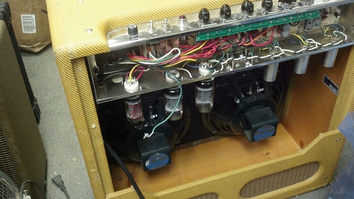
Removing the covers reveals a straight-ahead circuit board layout, with the tube sockets on another circuit board.  The input jacks had been replaced along with a few other components.

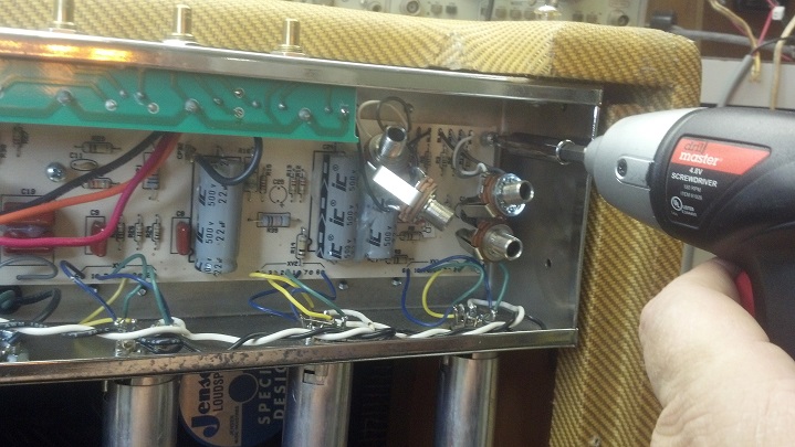
Removing the knobs and potentiometer nuts allows us to pivot the main circuit board downward so that we can work on it. The first order of business is to look for any workmanship issues, because this amp was built during the time when the factory transitioned from an assembly process using conventional solder to one using lead-free solder.

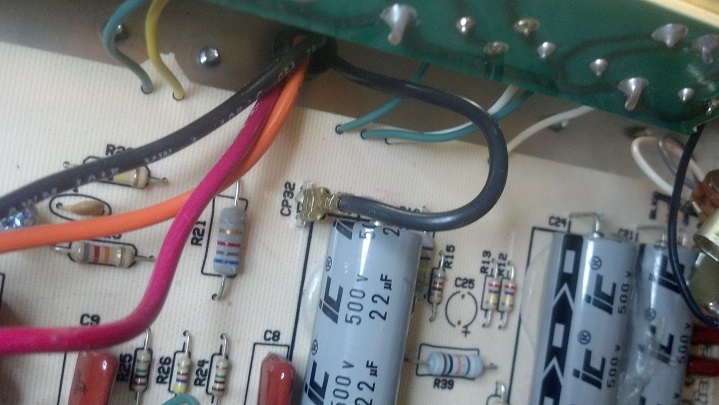
This is not factory soldering, but some later repair work. This solder joint will get reworked.

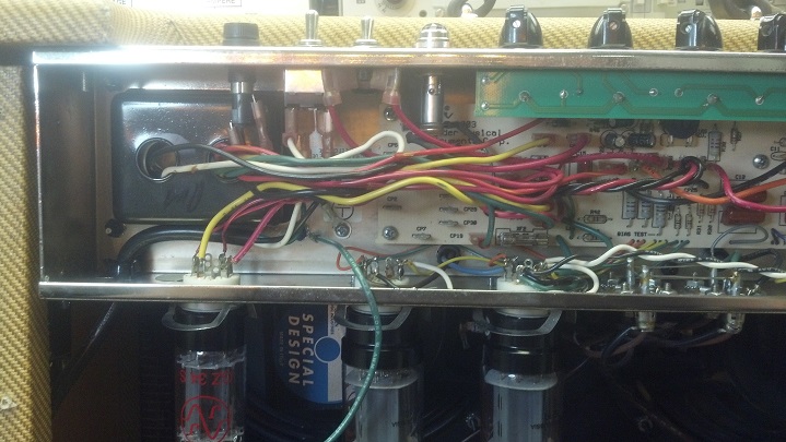
Flexing the circuit board in the vicinity of this ribbon cable results in a terrible racket from the loudspeaker. Something’s wrong here!

Following the cable, we found an unsoldered joint on one of the tube sockets. This is a factory workmanship problem.

After the missing solder joint was restored, the amp was still noisy. I captured some of the noise waveform on the oscilloscope display here.

Further troubleshooting revealed that the tone caps were noisy. Here are some new ones, right from Mouser.  The Orange Drop capacitors on the left are the correct value.  The darker capacitors on the right are epoxy dipped silver mica, very stable and will withstand the full working plate voltage in that part of the circuit.

C7 is the capacitor associated with the treble control.

C6 is part of the mid-range tone control.  C5 is part of the bass tone control.

C18 is in series with the volume control, was noisy, was the wrong value, and is now replaced.  This amp is VERY well behaved now.

Jacob jacks the Epi Les Paul into the amp to run it through its paces.  This is an amazing combo amplifier!

Jeff picks up his amp wearing his special T-shirt. Only musicians will get it.

Thanks for reading all the way to the bottom!

CONTACT – David Latchaw EE
281-636-8626

Fender Bassman LTD Tweed Factory Workmanship Problems

This beautiful reproduction amp worked well for a while, then began to exhibit strange symptoms. After quitting entirely, the owner called the Unbrokenstring Crew.   Can we fix it?  Yes we can!

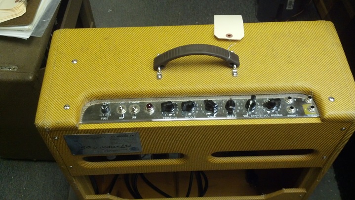
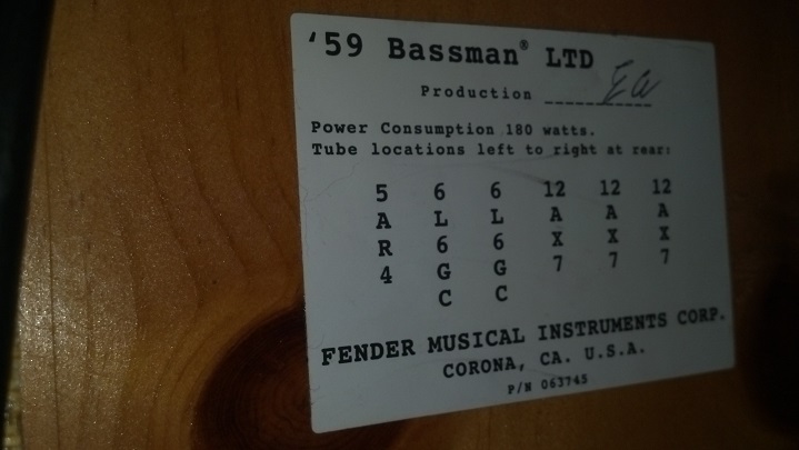
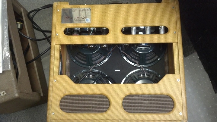
At first glance, this amp looks to be a chip off the old block. Other than the label on the back and the like-new condition, this amp is almost indistinguishable from the original model.

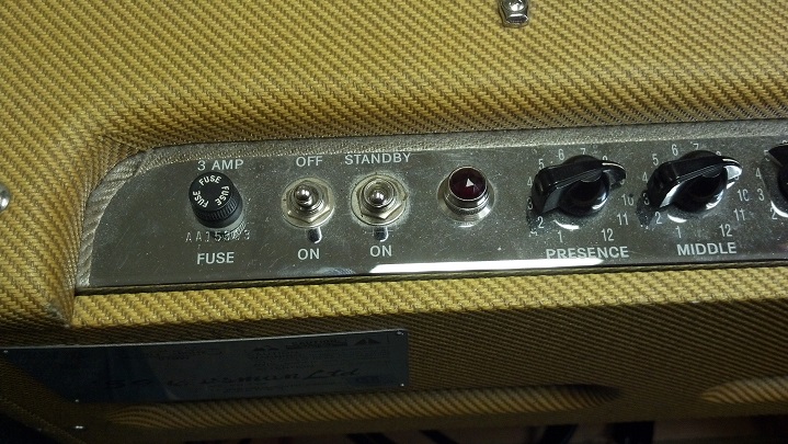
The lovely control panel lends a little mirror-like bling to the case.

WARNING: Tech porn. My, aren’t we starting early in the post with the porn?

The chrome faceplate shows every fingerprint.  This will need to be polished before the owner gets his amp back.

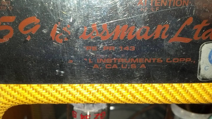
The silkscreen is a little worn off the nameplate but the chassis model is intact.

You can clearly tell that the cabinet is pine and not plywood nor MDF board.

WARNING – More Tech Porn – If you turn up the sound, you can hear some heavy breathing! Let’s fix this!

The rear panel is lined with aluminum tape.  The green wire grounds the foil to the rest of the chassis.

Here we see the hand-wired tube sockets.  Although I would like to have seen the control panel hand wired as well, this is overall the best way to build a tube amp, IMHO.  The dangling green wire is the ground wire to the foil seen in the previous picture.

The chassis wiring is a combination of wire-to-board and wire to flag terminals.  Two printed circuit boards are employed; one for the components in the amplifier itself and another one for the front panel control wiring.  Also note that the loudspeakers say “SPECIAL DESIGN.”  I’ll explain what that means later.

Here we see the input jacks and preamp tubes.  Sorry about the glare in the pics.

Let’s get that circuit board out, because I found a bad connection that requires solder rework.  The input jacks are already loose in this picture.

The nuts on the controls are called ‘small outline’ which is a nice touch that Fender added.  The small outline nuts will not show when the chicken-head knobs are installed.  Off they come!

Some sound came out of the loudspeaker when tapping around this area. What do you think we will find?

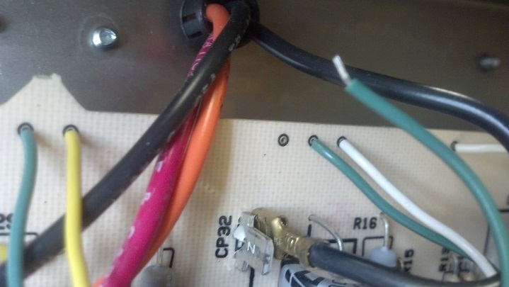
The stripped part of this wire may have been soldered at one time, but the solder joint failed. This wire pulled right out with nary a tug.

This grey wire also came out.  We need to remove this circuit board in order to do some serious work on the solder side.

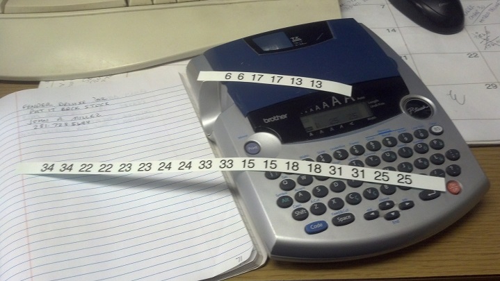
There are about twenty five flag terminals with wires on them that need to be removed in order to pull the circuit board out of the chassis. Each wire is marked with nomenclature that matches the identification information on the circuit board silkscreen. Here, I’m making numbers with my Brother label machine.

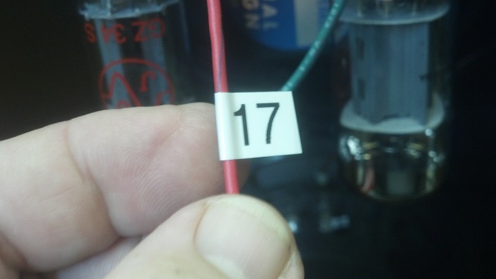
Each number was repeated so that the label could be read from either direction. Here, the label is formed into a flag and looped around the wire.

As I moved the wiring around to free the circuit boards, more wires came loose. I speculate that the lead-free soldering was performed at the wrong temperature or with a flux that did not allow the strands of the wires to be adequately tinned while the joint was formed. Over time, these failed.

Each failed solder joint was re-flowed with real tin/lead solder using activated rosin flux. This rosin flux is not conductive, but the dust it attracts is conductive. Rather than take a chance with future problems (and to keep my workmanship looking nice) the circuit board is manually de-fluxed.

There. That’s better. This is what the solder-side of this board should have looked like when it left the factory.

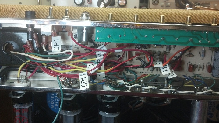
And now it’s time to put this amp back together. This is where all those wire flag markers come in handy.

Yes, REALLY handy.  There are a lot of connections to be restored and I would have had some issues had I not marked each one with a flag.

The amp is back up and running. Here’s a pic of the bias check. Can you see how many milliamps flows through the tube pair at idle?

Here’s a pic of our favorite green wire, seen in an earlier photograph!

One of the screws would not tighten, so here you can see that I’m blowing out the debris from the hole prior to plugging it and drilling the plug to hold the cabinet screw securely.

All done. Do you remember that I mentioned something about those ‘Special Design’ loudspeakers? Well, if you ever want to replace these loudspeakers with other units, Be Aware that the magnets on those new speakers will hit the amplifier chassis. Be very careful to replace these loudspeakers with ones that will mechanically fit. Just sayin…

Thanks for reading all the way to the bottom!

CONTACT : David Latchaw EE
281-636-8626

Octal Tube Base Replacement Experiment

This fine old 6V6 tube tested good, but the base was mechanically loose from the glass envelope.  Will the Unbrokenstring Crew be able to salvage this fine old Made In U.S.A. specimen?  Let’s find out!

Let’s unsolder the internal wires from the tube base.  These foam pads will protect the tube from the jaws of my vise.

To get the wires back in the right pins, I added an index mark on the socket and on the glass envelope.  The permanent marker is not permanent on the glass nor on the bakelite base, so we need to be careful not to wipe it off.

Once the solder is removed from inside the pins of the tube base, the envelope is easily separated.  Here you can see the glass neck that allows the air to be removed from the inside of the glass envelope, at which point the glass is heated and the neck is sealed.  The silver inside the glass envelope is from flashing the ‘getter’ to remove the rest of the oxygen and water from the tube envelope.

The glue used ‘back in the day’ varied by manufacturer.  It consisted of partially organic, varnish, rosin, and ground glass as a filler.  The finish on Stradavarius violins was not much different!

This chemical soup is pretty good stuff, as you can see that it is still adhering to the glass after half a century.  Not many modern adhesives can attest to that sort of performance, particularly where the difference in thermal expansion of the adhered materials is so different.

In this picture, I have soldered temporary wires which shall serve as extensions of the leads of the tube.  This will permit each lead to be aligned with its pin while the tube socket is reassembled to the glass envelope.

This is a little better view of how the extensions work.  Each blue wire is threaded into the corresponding pin as the tube is partially reassembled.

From 1950 organic adhesive, rosin, and ground glass, we progress to the 21st century.  This high temp gasket maker is designed for operation to 600 degrees F and low electrical leakage, suitable for automotive sensors.

The plan is to ensure glass-to-socket coverage of red RTV, with some additional red RTV inside the tube socket for mechanical strength.  I don’t want to get a lot of red RTV around the delicate glass neck, either.

Now we are ready for the big Red Squish!

We should have good red RTV coverage now!  The mess can be cleaned up later.

I left a fillet of red RTV around the top of the tube base.  Does everything look straight to you?

Our victim is left to cure overnight in a yoga position, to assure that the red RTV is intimate with the chakra.

We’re back in the clamp again, this time to remove the blue wires and resolder the original leads inside the tube pins.

The extensions are 30AWG wire wrap wire;  so small that just a touch of the soldering iron is enough to remove them.

Each pin is partially filled with solder with enough heat to assure that the internal leads are well-secured.

The transconductance of this tube is identical to what was measured before the base was replaced.  No electrical leakage current was measured from isolated pin to isolated pin using a capacitor leakage checker of the Heathkit IT-28 Capacitor Checker.  Then I installed this tube in my Gibson GA-30 for a final test.  Sounds good!  Takeaway from all this:  Don’t pull on the glass envelope of a tube when removing it from a socket!  Pull on the tube base.

Thanks for reading all the way to the end!

Contact: David Latchaw  EE

281-636-8626

Moss Custom Amp Head Surgery

What have we here?  A road case for The Deer Hunter?  Or perhaps a Big Buck Body Bag?  Let’s See!

Zach says his amp plays like crazy but one tube will red-plate.  The high voltage place power supply fuse will blow.  This cannot continue.  Can the Unbrokenstring Crew help?

Awesome dinosaur visuals dominate the Plexiglas window, and the Tolex deserves a closer look. Wow!

Five preamp tubes handle preamp duties on two input channels, driving two pairs of 6L6 tubes that can be split for half-power operation. No rectifier tube in sight, so I assume solid state rectifiers live under the chassis. I really like the beefy switches used for selecting the input voltage and setting the loudspeaker impedance.

This Tolex covering makes me drool like a noob. Just stare at it for a while. I am already dreaming up future projects that I will start just so I can cover them with this stuff. Yes, I know where to buy it in quantity.

This light show drew a lot of attention around the office. The Plexiglas is etched on the back side. Red LED light shines invisibly through the clear Plexiglas but scatters toward the observer’s eye when it hits the etched pattern. A small green LED makes a feeble attempt to illuminate the tubes. Extra Credit For You if you can see it.

A confirmed NO AUDIO condition launches some exploratory surgery. Based on the red plate report, we should look around inside before burning up any more tubes. This unit uses commercially-available parts throughout; the sticker for the output transformer lives on the chassis near the transformer itself.

Along the same lines, AC power conversion is handled by this off-the-shelf transformer. I really like how Moss has done this ‘build.’

A fresh fuse of the proper ratings now lives in this fuse holder. If you ever do this yourself, BE AWARE that voltages and currents at this point are LETHAL, even with the power cord unplugged.   This fuse is not considered a user-serviceable component for this reason.

The high voltage rectifiers and filters are on the upper eyelet board.  Low voltage DC is rectified so that the preamp tube filaments are always fed direct current.  A 5v power source for LEDs and control switching is found on the lower eyelet board.

The circuitry for the preamp tubes are to be found on the lower center eyelet board.  If I had done this amp, I don’t know that I would have done a thing differently!  Well done, Mr. Gelinas!

Can you say that you have made something that you were proud to sign you name to it?

We’re up and running with a set of shop spares fulfilling the role of output tubes.  During the second day’s test run, power consumption increased slightly, then things started happening quickly.  I shut the amp off as the third tube from the left began to get hotter than usual.  I did some circuit checks, then restarted the test.  Later, the same thing happened again.  I moved tubes, no difference.  But the problem didn’t happen every time.  Turns out, I had a parasitic oscillation that occurred only in tube 3.  Sorry, no oscilloscope pics, but they come later.

Parasitic oscillations may occur whenever energy storage components (capacitors, inductors) are used in gain circuits.  Parasitic oscillations are rare in audio circuitry, but can happen.  The inductor hidden in this picture is in the form of the wire wound cathode bias resistors, seen here as those white rectangular items in this picture.  These happen to be made by Xicon, the inexpensive Chinese house brand carried by Mouser Electronics.

The white Xicon resistors have been removed and replaced with these non-inductive wire wound resistors of the same resistive value and wattage.

These resistors also came from Mouser, and just cost a few cents more than the Xicons that are now in the bottom of my trash can.

Now that I have some confidence that we have a handle on the root cause, we’re installing a fresh set of JJ Tesla 6L6 which is what Moss used when they built these amps.  And I have a local dealer.

This is my favorite part of the job!  It’s beginning to feel a lot like Rock and Roll Time.

This is what 100 watts into a non-inductive eight ohm solid state load looks like with a 440 Hz (concert A) sine wave running through the clean channel into four paired push-pull 6L6 tubes.  No fans were used to conduct this test.  The Moss amp is conservatively engineered and can do this all day long.

Now for some bling.  These high-intensity white LEDs are super-glued into these brackets.  I wonder if this amp was a prototype?  I didn’t ding up these brackets getting them out.  They came that way.

To add some real intensity to that anemic internal illumination LED, this is a high-intensity blue LED I ordered for the occasion.

The aluminum bracket makes an excellent heat sink for the new high intensity LED.  I just used heat shrink tubing to keep it in place and to insulate it electrically where the wiring is attached.  The red connectors are male/female spade connector pairs that replaced the original ‘low-boy trailer light’ connectors Moss used, which I replaced because they were becoming intermittent.

Betcha’ can see this LED now!

LEDs check out.

In order to increase the current to the values needed by the white and blue LEDs, small appropriately-rated resistors were placed in parallel to the original LED bias resistors.  Remember that the value of two resistors in parallel is equal to the reciprocal of the reciprocal of their sums.

Wood screws hold the edge light LEDs in place, so that the LEDs shine into the Plexiglas.

A little black paint touches up everything so it appears that no one was here.  All wiring is new, with black insulation.

This is the finished product.  The blue light is really working for us to show off the interior, and the white illumination of the engraving is just what Zach wanted.  This works better with his white Tolex cabs.

Zach moved to Knoxville TN before the amp was ready, so I’m shipping it to him in two boxes.  One box holds the head in the case and the other box has all the breakable glass in it.

Here’s the glass.  Most of this box will be bubble pack.

This is the box of tubes.  Time for a cup of coffee, and another larger box to protect the glass!

Most ATA flight cases have foam, but this head case had none.  I’ll make do with bubble pack.

Good practice for Christmas!  This is the only pic I have of the rear cover panel installed.

And now we have gone full-circle, to the Big Buck again.  One more step!

Jen is holding the shippable box containing the glassware, and the case with the amp head is in the larger box.  Off to Knoxville where Zach has gigs and a contract waiting for him.  Best of luck to everyone!!


Thanks for reading all the way to the bottom!

David Latchaw, EE

281-636-8626

Vintage Tubes in a New Fender Blues Junior

The owner of this current-production Fender Blues Junior selected ‘vintage’ preamp tubes in search of the ultimate guitar tone.  A short time later, the amp doesn’t play at all.  This was not supposed to happen!  The Unbrokenstring Crew rides to the rescue to determine what happened.

This amp is less than a year old and is in excellent shape.  Let’s take a look inside to see what’s going on.

The first two preamp tubes are not JJ Teslas.  The customer said that he ‘had a buddy with a tube tester’ that sold him these ‘vintage’ tubes to give this amp that ‘vintage’ tone.  No kidding.

Oops, I did it again!  More amp porn.  No point-to-point wiring here.  This circuit board is a single-sided board with soldered jumpers to cross over traces.  Nothing wrong with this construction as it it mass-production-friendly.

How is this for ‘vintage?’  An honest-to-God made-in-USA tube branded RCA.

And how’s this for ‘vintage?’  Realistic is a Radio Shack brand.  They used to offer a ‘lifetime’ warranty on the tubes they sold.  Now, if you walk into a Radio Shack store, they don’t know what a tube is, and they will try to sell you a cell phone contract.  How things have changed!

The RCA tube failed in the tube checker in a rather unusual manner.  So here’s it’s new replacement.

The Radio Shack ‘Realistic’ tube was in excellent shape when tested on the checker, so I think we can safely say that the RCA tube was the root cause of ‘why this amp didn’t play’ anymore.

We’re all back together and playing.  But what would the customer think about losing his ‘vintage’ tone tube?  I showed him the video at http://youtu.be/ZYKISIQvBmw and he was all of the sudden very satisfied with the new tube and the tone of his amp!


Thanks for reading all the way to the end!


Contact:  David Latchaw EE

281-636-8626