Ibanez TubeScreamer Pedal Repair

Steve said that his Keeley-modded Tube Screamer pedal had quit.  Could the Unbrokenstring Crew bring it back to life?

This pedal is in great shape cosmetically!

Robert Keeley made a few circuit changes that are well-documented on the Web.  This pedal has those changes.

The battery box has its own lid.

The bottom of the pedal is shielded with the metal screen seen in the center.

A die cut sheet of black insulative material protects the circuit board from the metal shield.

Let’s get it all out of the enclosure so that we can work on it.

We’ve applied battery power and connected up to my Marshall Stack.  The original problem is still with us.

An oscilloscope probe verifies that the dual operational amplifier is defective.  Part of the Keeley mod specifies a Texas Instruments 4558 dual op amp.  This IC is socketed, so replacing it is trivial.

Here is an example of the softly clipped audio that the Tube Screamer delivers to the amp input.

Reversing the disassembly procedure is all we need to do to get this cool little pedal back together again.  We’re done.

Thanks for reading all the way to the bottom!

CONTACT – David Latchaw EE
281-636-8626

JBL SoundFactor SF12M Loudspeaker Repair

Sal is a busy DJ who had to use his backup system after one of his JBL speaker cabinets quit. Can the Unbrokenstring Crew help get him back on the air?

This loudspeaker has been a reliable performer but had lost its high-end, then quit entirely.

So we found this inductor inside the cabinet, probably part of the crossover.  This is the ‘quit entirely’ issue.

The grille and loudspeakers need to come out to get access to everything.

This horn driver is Made In The USA!

This pic documents the wiring polarity.  One yellow wire is solid and the other yellow wire has a black stripe.

All we are measuring across the horn terminals is the crossover impedance.  This is the ‘lost its high end” problem.

This speaker is also Made In USA!

This is a pic to document the loudspeaker wiring.  One of the green wires has a stripe.

This loudspeaker seems to be OK.  No dragging or other issues were noted.

The loudspeaker wiring was bundled up to make it more compact…

so that we could remove the crossover network and repair the missing inductor issue.  This is a simple soldering repair and has been covered elsewhere in the blog.

The date of manufacture of this assembly is stamped inside the unit on the bottom of the cabinet.

Some of these horn drivers are repairable by the end user.  Let’s see what’s involved with a repair.

The threaded horn adapter comes off when four screws are removed.

The voice coil can be removed from the magnet as shown.  This voice coil assembly is widely available from many Internet vendors, Amazon, and eBay.  This is a repair that you can do yourself if you are handy with hand tools.

I searched for this JBL assembly number and found the whole assembly on sale for about the same price as the voice coil.  And, it comes with a warranty!

This horn driver has a higher power rating than the original OEM part.  These are made in Brazil now.

Oh, and did I mention that it came with a warranty?

This dust cap keeps junk out of the interior diaphragm of the horn driver.

The new driver even looks cool.  Too bad it’s hidden inside the loudspeaker cabinet.

The assembly fits in the loudspeaker without modification and is compatible with the existing wiring harness.  The thread pattern is compatible with the horn lens.  It just screws on by hand without tools.  What’s not to like?


Another happy customer!

Thanks for reading all the way to the end!

CONTACT – David Latchaw EE
281-636-8626

Boosta-Grande Pedal Repair

We did a quick-and-easy foot switch repair on this gain pedal.  Here’s the scoop:

The operation of this pedal was intermittent.  The switch didn’t click anymore.  Yup.  Probably just needs a foot switch.


The foot switch is on its own circuit board.  This switch is a latching, 3 pole double throw unit.  A ribbon cable carries all the lines between the terminals of the switch and the rest of the electronics.


The circuit board was carefully de-soldered using braid wick and lots of flux.  We’re ready for the new switch.


Here is the switch…  or what’s left of it.  The pedal enclosure was holding everything together.


The new switch was installed so that a minimum amount of threads were exposed on the top side.


The switch was adjusted so that the terminals on the switch lined up with the slots in the circuit board.


Everything lines up where it should.  See, I said that this would be easy!


The chef ordered new solder fillets all around!


An easy fix, and this boost pedal is VERY clean.  We’re done here!

Thanks for reading!

CONTACT – David Latchaw  EE
281-636-8626

DigiTech TSR-24 Repair

This stereo rack mount effects processor had a couple of problems. When turned on, the display would flash. And the rotary encoder is busted.  And we really need to get this fixed this week.  And many parts are obsolete.  Can it be fixed in time?  The Unbrokenstring Crew to the rescue!

These units are, in my opinion, highly-under-rated. When they work, they sport an innumerable list of effects. When they don’t work, they are still prized for spare parts.

This unit needed a new rotary encoder.  If there is one mechanical design problem, you are looking at it.  This big knob sticks out farther than anything else on the front panel, and therefore takes a beating if the unit is abused.  And, of course, this exact part is not available anymore.  Let’s open up the unit and go to work!

A firmware upgrade kit is still available from an eBay vendor, that adds delay time and new effect algorithms.  The new parts go here.  This unit will not be upgraded at this time, but if you are considering the upgrade, it’s not difficult at all.

More tech porn.  This is a custom processor flanked with other members of the DSP chipset.

We need to remove the circuit board entirely from the chassis in order to replace the failing voltage regulator.  These nuts and washers all come off.  Fortunately, they are finger-tight.

Interestingly, the screws holding the front panel in place are Allen head cap screws.  They look very cool.

More Allen head cap screws secure the external heat sink.  The voltage regulators are behind this heat sink.

Just documenting where all the cables go.

The configuration of the wiring harness determines if the particular unit is 115vac or 230vac.  No switches or jumpers!

This pin was loose in the circuit board.  We’ll repair this solder joint when we get the board out.

OK, I think I got it out.

The voltage regulators are inside this sandwich of aluminum channel.  The big heat sink seen in a previous picture bolts behind the aluminum angle bracket, seen at the top of this photo.

With the top piece of aluminum channel gone, the voltage regulators are easily accessible.  DigiTech used a grey silicone pad underneath the regulators instead of messy grease.

The new regulator is soldered in from this side.  Can you tell that the three joints to the right are ‘shinier’ than the others?

The aluminum sandwich goes back together.

Now that the mechanical sandwich is secure, I am reflowing the solder joints to remove all mechanical stresses.

The loose pin seen earlier was not the only issue.  Two pins fell out of their holes!

The solder joints beneath pins at Q11 and Q12 were re-flowed with rosin solder.  The flux seen here will clean up with isopropyl alcohol.

This sub-assembly, called the “Pot Board,” carries the rotary encoder, the control with the white shaft seen in this pic.

That’s the problem!  Of course, this part is no longer available.

Here is a better look at the damage.  When the knob is banged inward, the phenolic circuit board used to implement the rotary encoder takes most of the stress.

Let’s clean up this mess.  No sense in leaving the broken pieces in the unit!

I prefer braid and rosin to clear out plated thru holes in circuit boards.

The plan will be to transplant the white nylon shaft and bushing into the new encoder body.

The new rotary encoder was dis-assembled.  The old shaft assembly is on the left, and will mate directly with the circuit board.  Note that this rotary encoder has a different land pattern than the original.  This circuit board will make fewer pulses per revolution.  In my opinion, slowing down the action of the knob is a Good Thing on this unit.

Here’s the completed “V’Ger” rotary switch.  The tabs on the back hold everything together, assimilating the two encoders; a tip of the hat to the Star Trek movie when the Voyager space probe ‘merged’ with an alien probe, then returned to Earth to ask the question, “Who’s my daddy?”

Here is a good view showing how everything lines up.

The new encoder board has a slightly wider pin spacing, but nothing that will keep us from finishing this project.

Here is the pot board assembly with the new encoder assembly installed.

That pot board assembly shoe-horns behind the front panel.  All the electrical connections are made thru the ribbon cable.  The cable needs to be mated first before the pot board is installed, because it won’t mate after the board is installed.  Don’t ask me how I know that…

Now everything fits.  This is a good view of the little bit of gun-smithing necessary to get the new encoder board onto the site on the pot board where the old one was located.  We’re on the home stretch!

Re-using the original shaft and bushing allows us to stay with the original knob and hardware.

The instructions to perform a factory reset are freely available online and in the manual.

All done!  No flashing display, and the rotary encoder knob steps through all 255 different banks of effects at a sane rate.  This unit is ready for another decade of duties around the studio.

Thanks for reading all the way to the end!

CONTACT – David Latchaw   EE

cell – 281-636-8626

Seymour Duncan Twin Tube Classic Pedal Refurb

This pedal was making a strange, whooshy noise. Could the Unbrokenstring Crew fix it? Let’s find out!

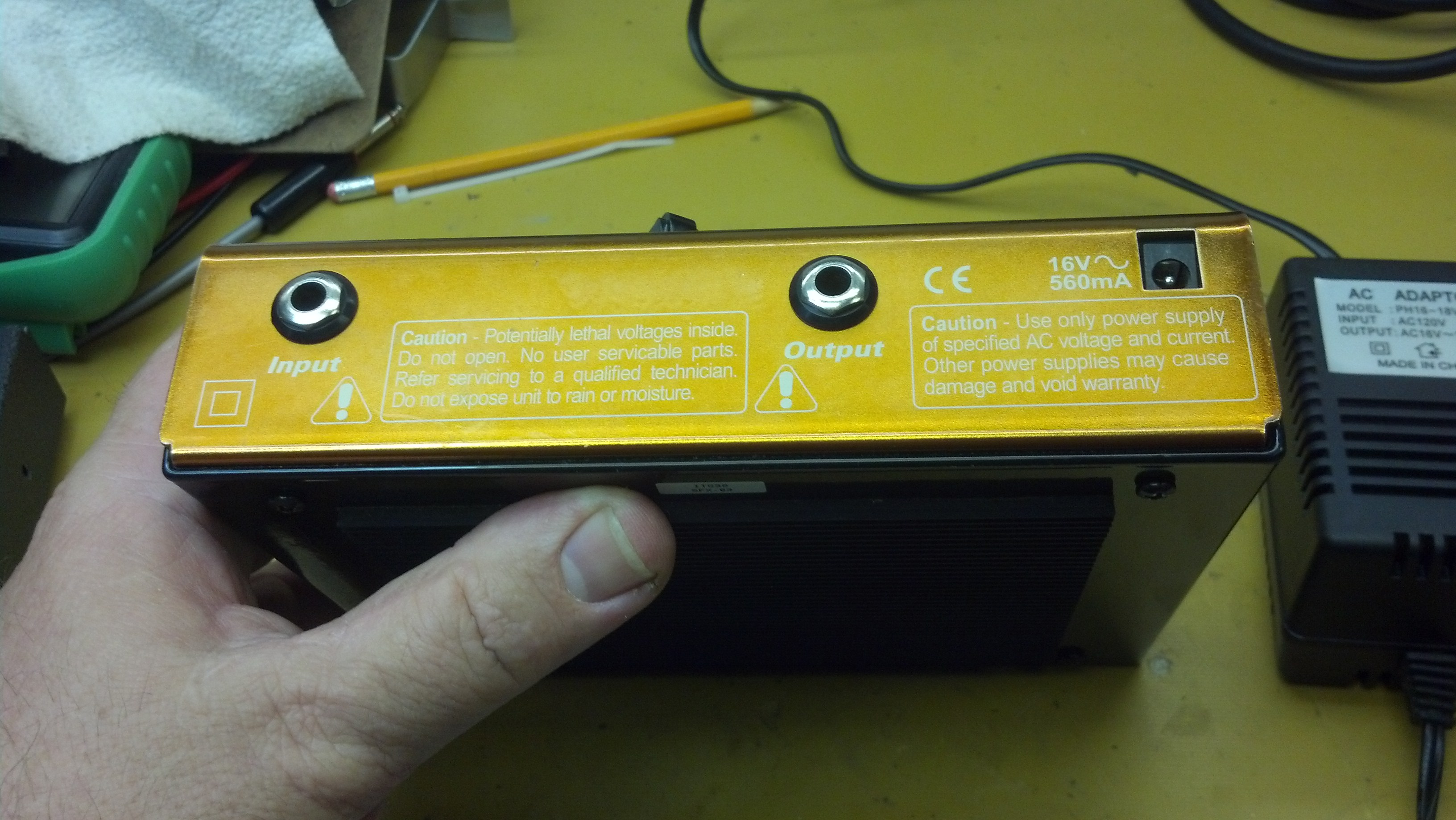
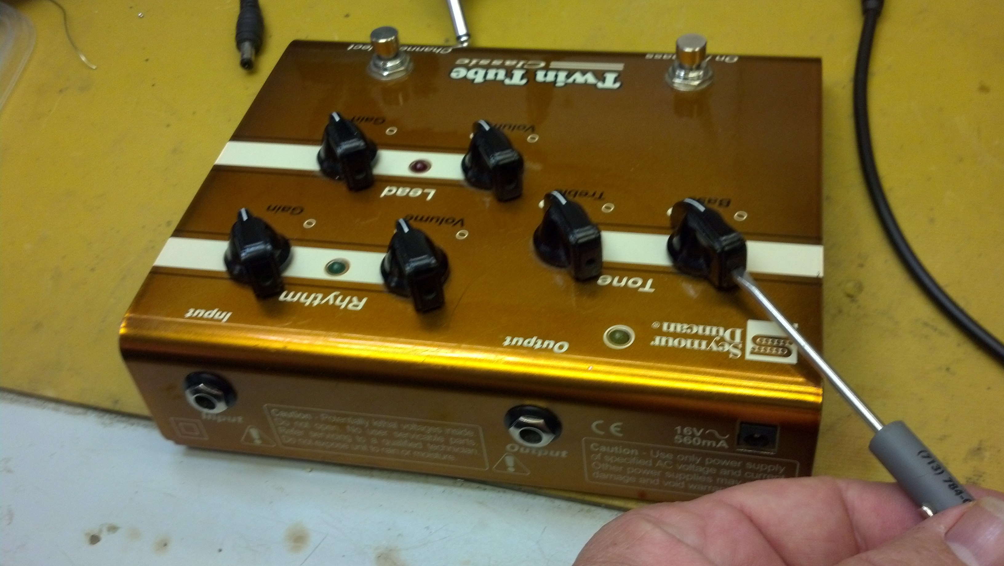
There are many pictures on the Web of the top of the pedal, but nothing about the back. Here it is! We haven’t missed much.

The bottom of the unit slides off. Four screws hold the bottom plate on the unit. I love that big non-skid pad on the bottom of this pedal!

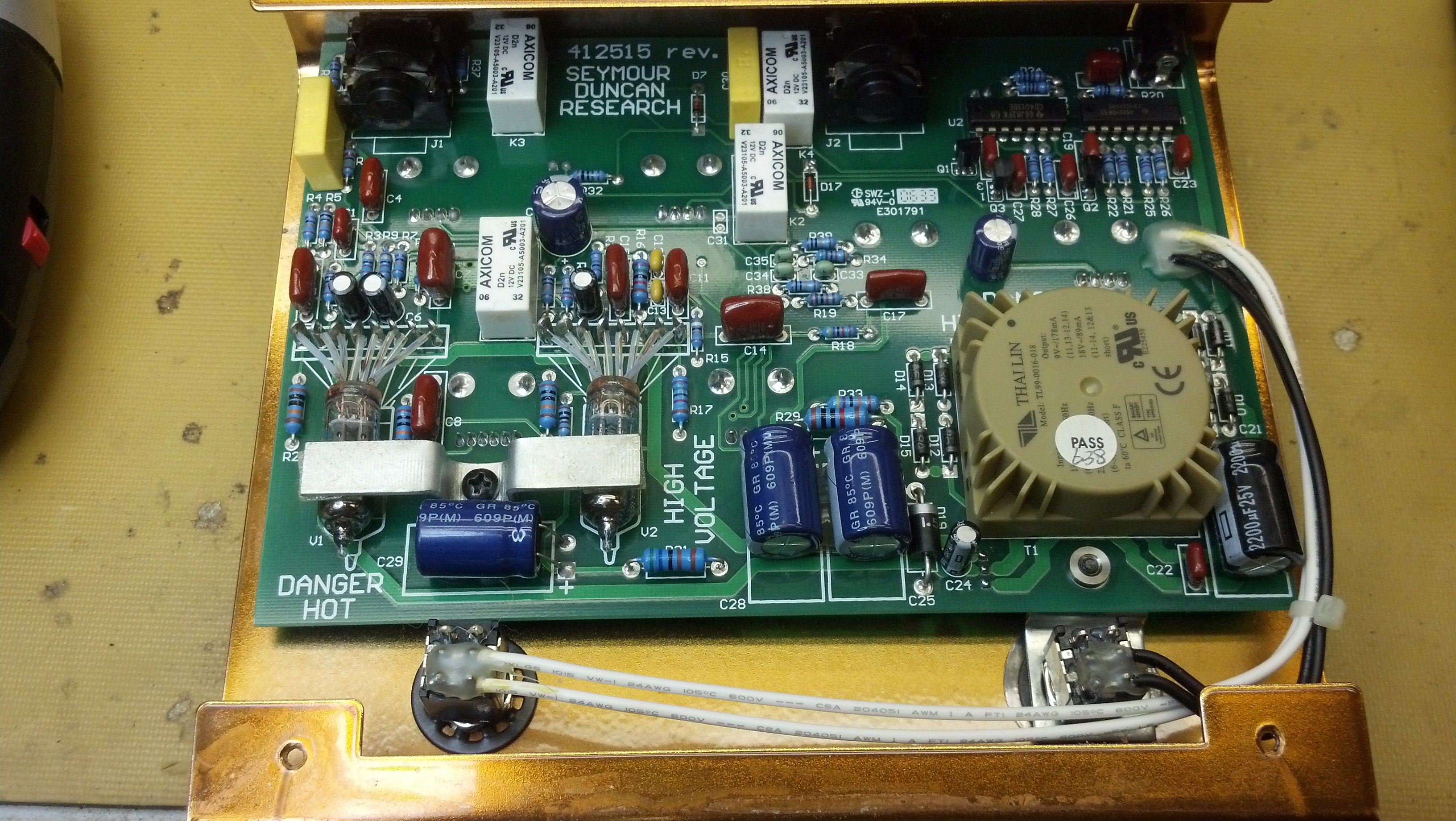
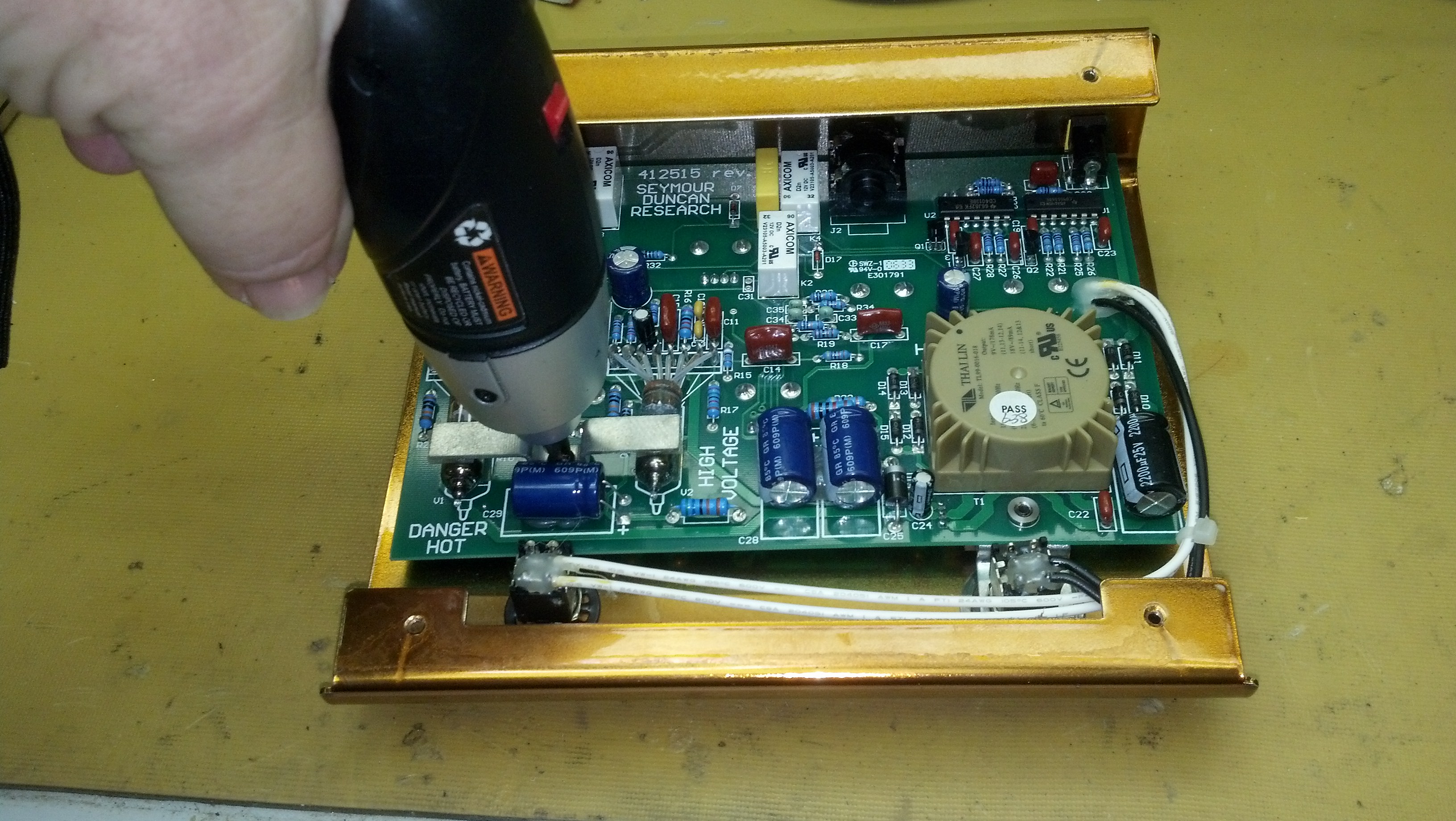
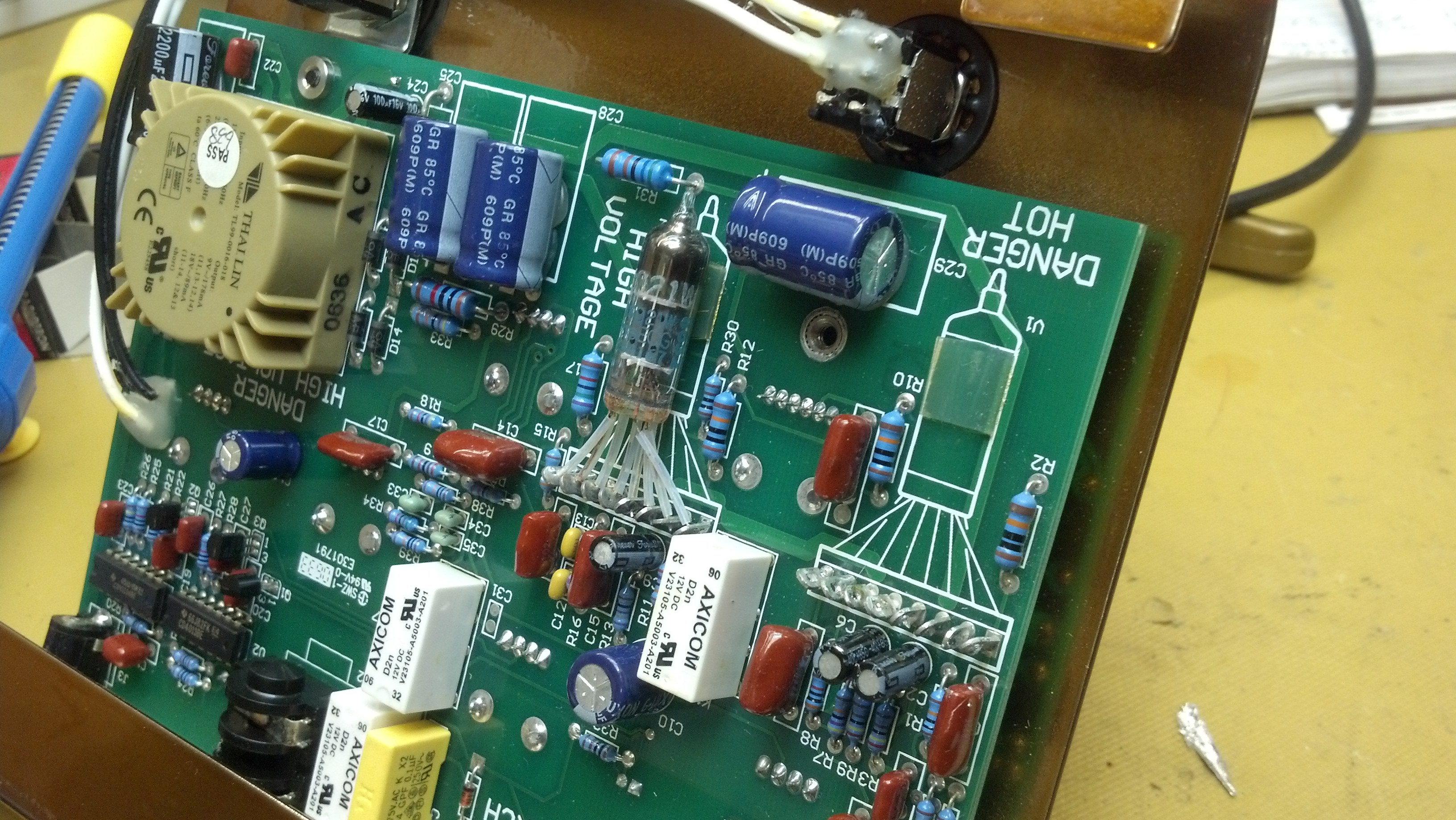
An interior view shows the pair of 6021 tubes and the circuitry to support them. Most everything else is switching, tone and volume controls.

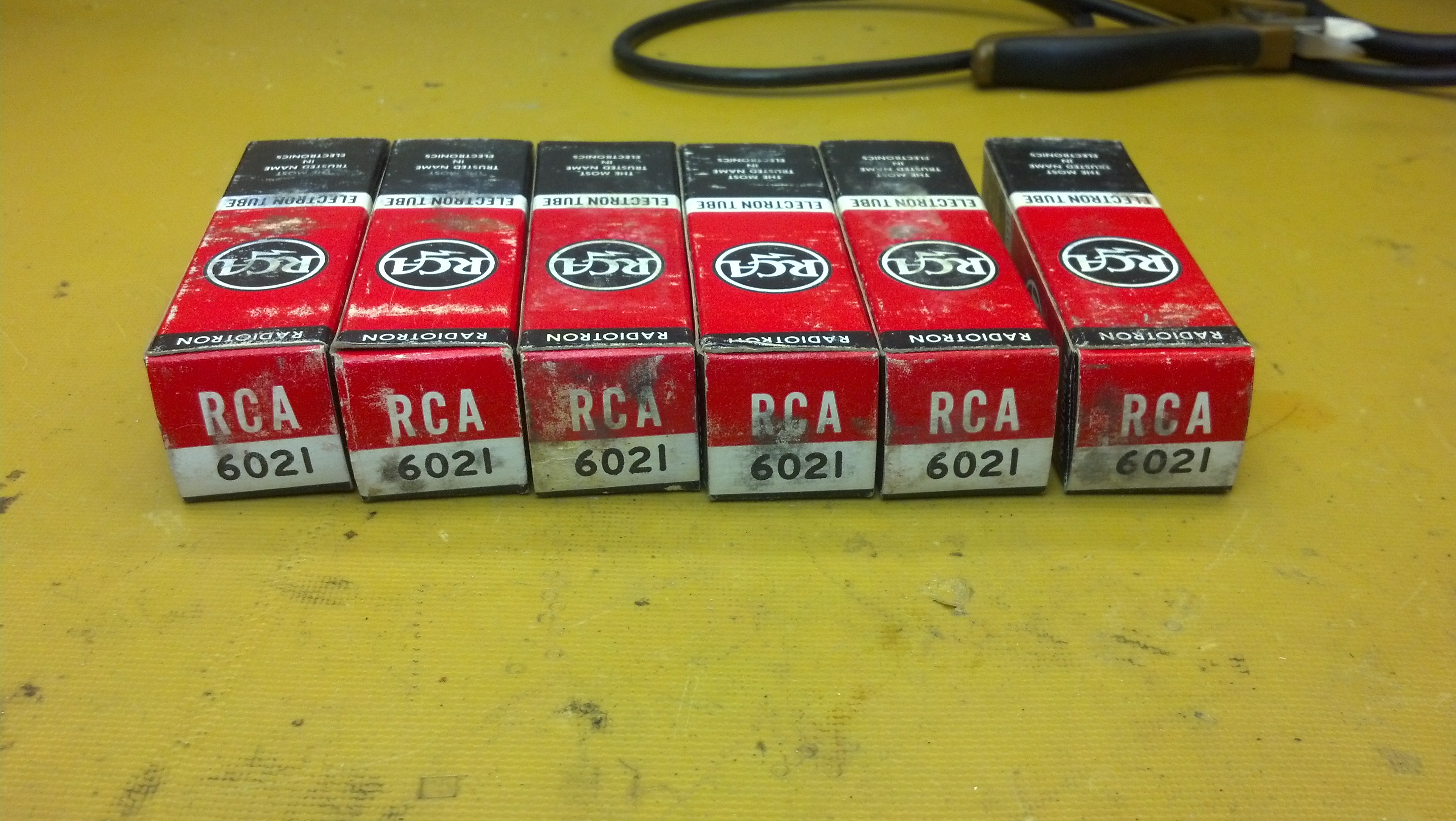
I located a stash of NOS RCA 6021 tubes from a resale shop on eBay. I purchased all they had.

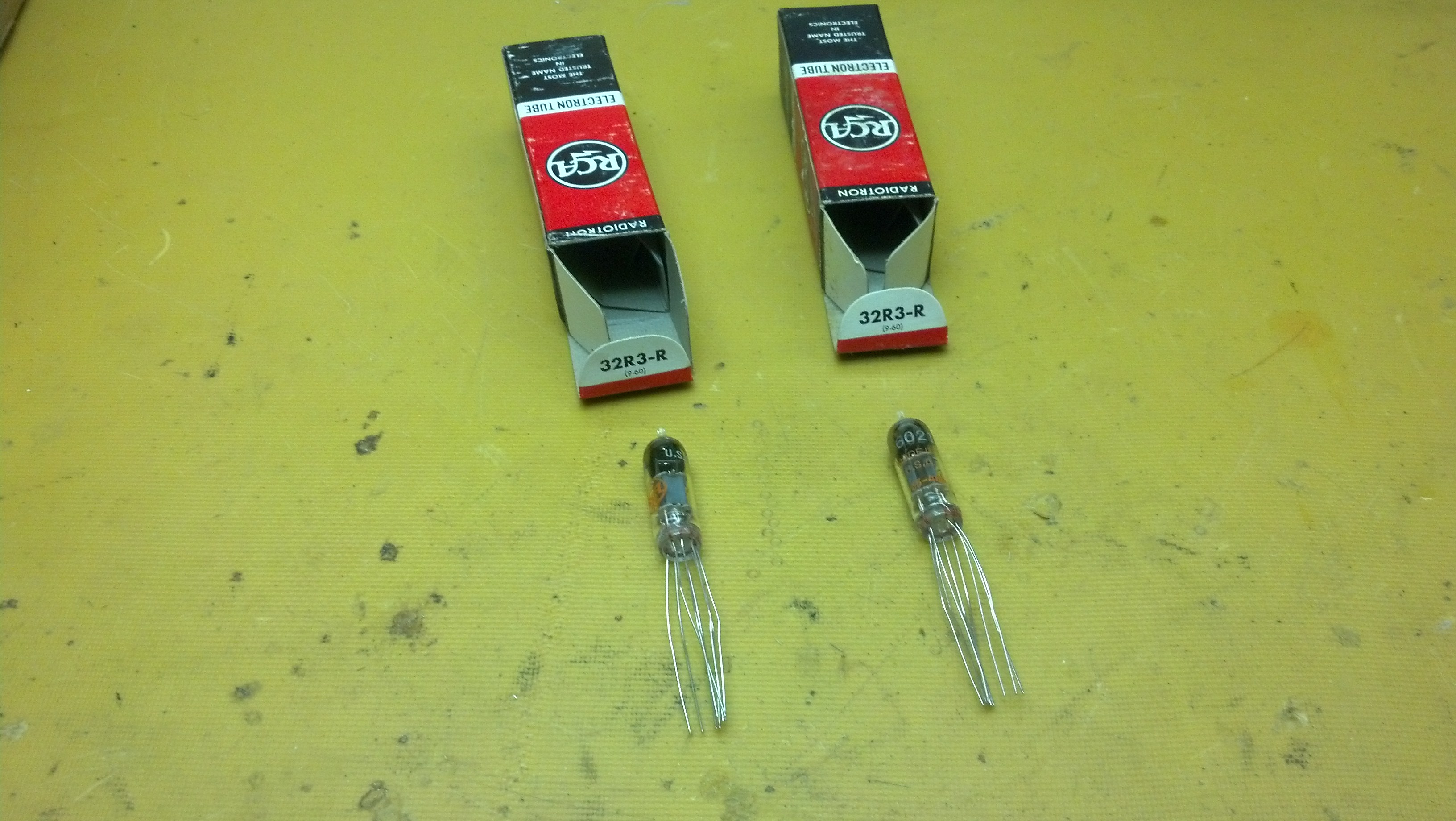
Here are two volunteers from the group.  The individual wires are soldered to eyelets, rather than having pins that fit in a socket.

One screw removes a bracket that holds the tubes in place.

I cut one of the old tubes out, then unsoldered the pc board terminals.

This is a roll of Teflon tubing.  Some of this will be slipped over each lead of the tubes to keep them from touching each other.  This stuff dates back to my NASA days.

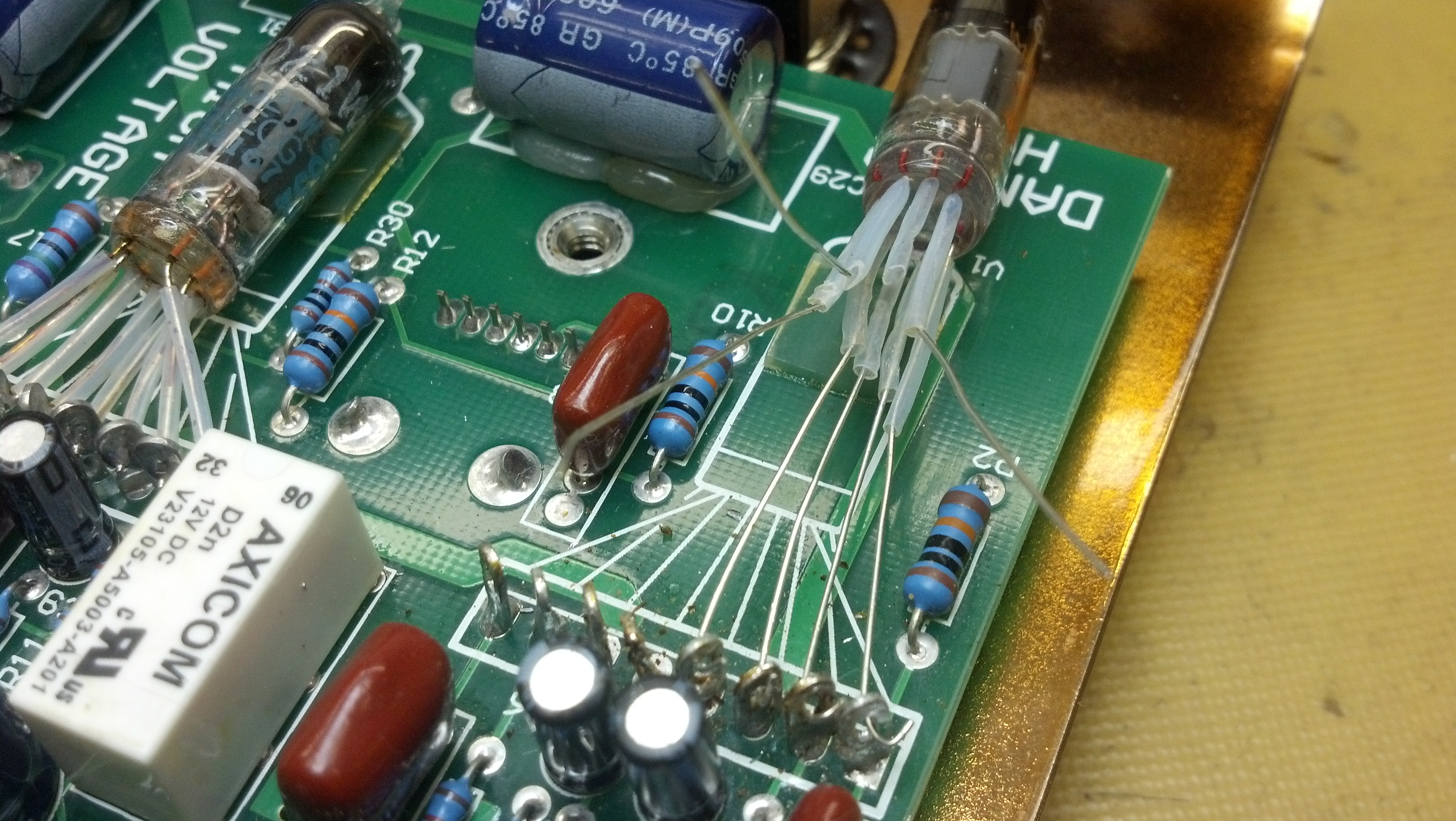
Pieces of Teflon tubing are cut to length and slipped over each tube lead.  The leads are then threaded through the holes in the eyelets, where they will be soldered.

Just a couple more leads to thread into the eye of the needle!

Each lead is pulled through the eyelet until the tube is seated in its final resting place.  Each wire will be hand-soldered and the excess lead trimmed.  As you might suspect, the second tube is replaced in a similar manner.

Having all the knobs pointing the same direction is a nice touch.

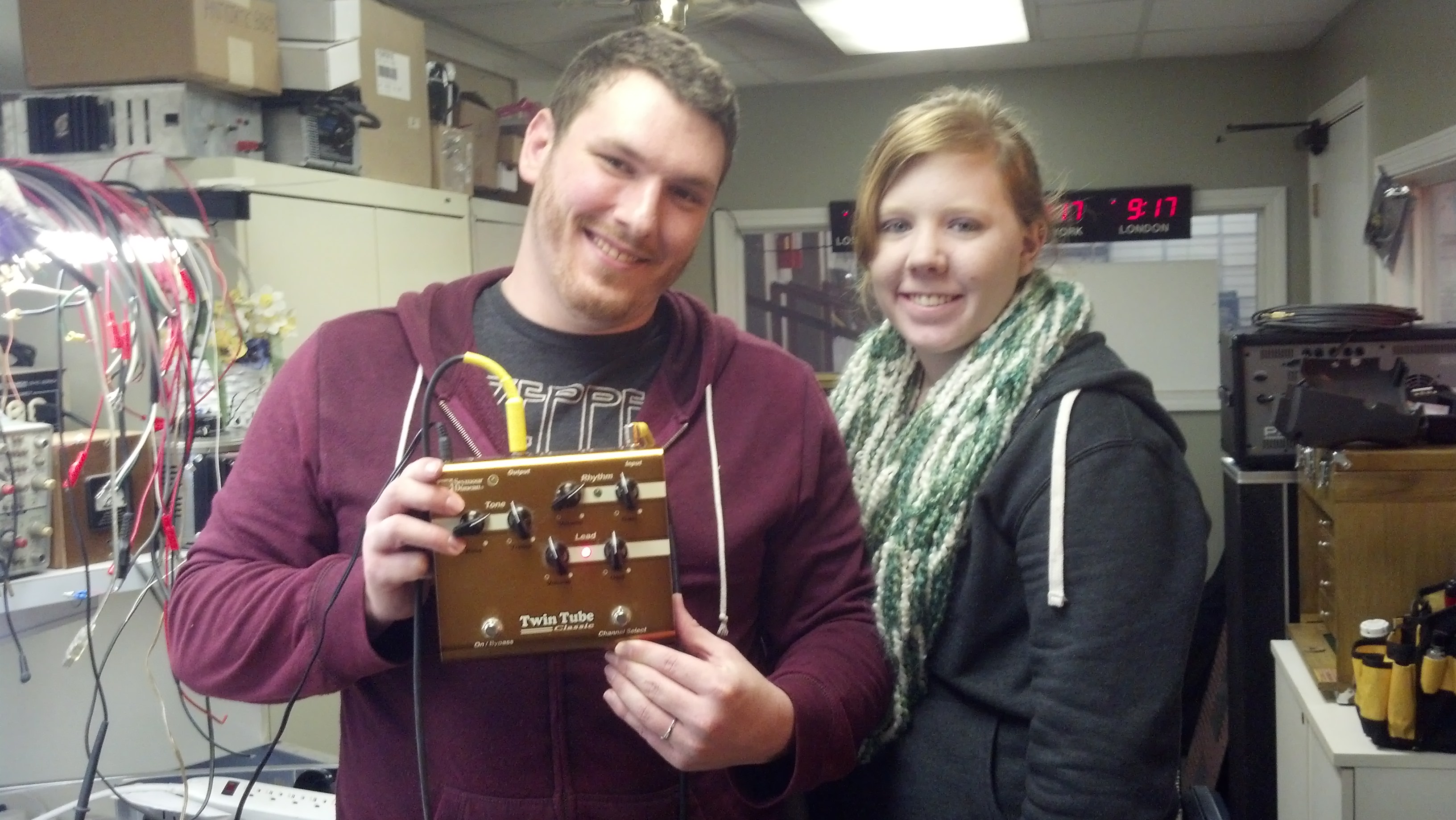
Sean and his beautiful bride pose for a pic!

Check out

http://www.facebook.com/asthecrowcries

and support these folks!

Thanks for reading all the way to the bottom.

CONTACT : David Latchaw EE
281-636-8626