WARNING – A very long blog post awaits you. Typical guitar amplifiers can be described in terms of functional blocks – power supply, preamplifier, power amplifier, and loudspeakers. This refurbishment effort left NONE of those blocks untouched. Sit back and enjoy!

This Peavey needed some work before it could be added to David’s tonal arsenal.

I removed the chassis for inspection. This is the ‘clean’ channel. The LEDs illuminate to show channel selection.

The ‘effects’ channel has a little more tonal control.

This unit uses an odd solid state phase shifter scheme and a mechanical reverb unit. The standby switch is on the front, and the power switch is on the back. The Fender switch scheme for tube amplifiers sometimes puts both switches in the back, and of course, I always select the wrong one because I have to reach around where I can’t see to work the switch.

Somehow, the 8 ohm jack is open-circuit. We will need to look at this on the inside of the chassis.

This is the main power switch. The ‘ON/ON’ function allows the user to capacitively couple the chassis to one side of the AC line. This sometimes helps with hum reduction, although the three wire AC cord defeats one side of the switch.

The fuse is intact insofar as the red pilot light turns on when power is applied.

However, this 10A fuse is the wrong part. Someone has been jacking with this amp!

Sorry, this needs to be fixed.

Note that the scratches on the tube base indicate that the tube was inserted incorrectly. How can this be?

This is how. The guide posts were broken off.

The reverb tank bag is screwed down to the bottom of the unit.

Everything here is intact, no damage, transducers are OK. We’ll set this aside in a safe place for now.

We found the first bug. Poor little spider.

All of the high voltage capacitors show signs of venting. See the little bump in the black rubber, next to the 350?

The output jacks on the rear of the chassis have been damaged.

The pin contact has been bent all the way out so that the plug cannot touch it.

This pic is to document that these inside star washers should be placed between the jack and the chassis.

Both jacks shall be replaced with new ones.

All new hardware was used, of course.

The jacks are wired together and the jacks are wired directly to the output transformer.

The amplifier circuit board has seen some significant pyrolysis. Maybe this happened when the tubes were installed the wrong direction, because of the missing guide posts?

To remove the amplifier circuit board, the tube socket pins must be unsoldered and the wires removed.

With a little attention to detail, the circuit board comes off the tube sockets.

This is the underside of the amplifier circuit board. I wonder if someone poked the wires a little too far, so that the ends touched the chassis?

This printed circuit board will be rebuild, and all the components will be moved to the solder side of the board.

Lots of rosin flux was used to clean off all the solder. Lots of alcohol is used to clean off all the rosin flux.

The rag gives some place for the mess to go.

With the circuit board cleaned up, we can see if it can be repaired. It’s too old to replace; Peavey has no stock.

The carbon tracks are removed. The remaining copper is trimmed back to where it is still attached to the laminate core.

Comparing the circuit board to the layout, we can verify where the traces and components actually should go.

Both sides of the circuit board are now spotless.

The new components will be placed above the surface of the board to allow for cooling and to insulate each part from the live circuit traces below each component.

The copper around the mounting hole is gone, so the lead of this component will be sweat soldered to the surviving trace.

To bridge the gaps in the copper, bare solid wire will be soldered in place, and insulated from the rest of the circuit with this Teflon tubing.

Here is a picture of the Teflon tubing at work.

All of the components are installed now. The Peavey Deuce uses four 6L6 tubes but only had two screen resistors; the other screens were tied to the plate voltage. The Peavey Mace amp uses six 6L6 tubes and has six screen resistors. I went with four screen resistors, as I believe that using two was an engineering oversight. The original Peavey documentation was ambiguous on this point.

This is a nice side view of all the components, flying above the printed circuit board.

Subsequent testing showed that the original phenolic tube sockets were either contaminated or were carbon tracked. The old sockets need to be replaced. Here, we’re drilling out the pop rivets that hold the sockets onto the chassis. Note the magnet, which attracts the steel shavings and keeps the mess to a minimum.

These tubes hang base side up, thus the base clamps keep the tubes firmly in the socket. As we know, heat rises, so the sockets get hot during normal operation. These were cooked.

The new sockets will be held in with #8 stainless fasteners. Here, the chassis holes are enlarged to pass a #8 machine screw.

Likewise, the holes in the new ceramic sockets need to be enlarged to the same extent.

The sockets will be mounted from the chassis. We won’t have any access to the bottom of the socket once the printed circuit board is soldered onto the socket pins, so I need some captive hardware permanently mounted to the socket ears.

These small outline nuts are brass with a silver plating. They solder easily to the ears of the new tube sockets.

Once the nuts were tacked into position, a nice fillet of solder is run all around the nut to keep them in place.

These new ceramic sockets are ready to be tacked into place on the circuit board. Pay attention to the direction of the index slot!

Here are the new ceramic sockets in place on the refurbished amplifier circuit assembly.

The new sockets and tube clamps were installed with the stainless steel hardware. To assure that the solder joints under the sockets will not be under stress during operation, a spare octal base tube is plugged into the socket to align the socket contacts before each solder joint on the amplifier pc board is made.

Here is the refurbished amplifier circuit board assembly in its final resting place.

All the high voltage power wiring, filament wires, and signal wires are in place and ready to be dressed.

The power supply circuit board had many bad parts. The large square resistor seen here was open-circuit!

And, when that large resistor died, it got really hot!

These large round flameproof resistors are available online as a better-than-factory replacement.

Nearly every component on this assembly was replaced.

We have 488 volts DC with no load on this assembly. That will be acceptable.

The power supply board is back in place, and the cabling dressed.

On the preamplifier board, many of the electrolytic capacitors were showing their age. The one of the left vented.

To remove the preamp board, all the knobs come off (of course.)

The felt glued on the face of this socket protect the faceplate from damage.

The preamp board is free from its moorings.

There appears to be little wrong on this side of the board assembly. There are no signs of prior repairs here.

The vented electrolyte from this electrolytic capacitor attacked the copper lead of this capacitor and ate through it.

These cement resistors were bad.

The new resistors were mounted off the face of the board, to improve reliability.

The controls were flushed, dried, and re-lubricated.

This hybrid amp uses solid state techniques for low-level amplification and tubes for high level amplification. These two transistors were bad. These driver transistors are part of the phase splitter circuit, and drive the tubes directly. The replacement transistors have a different pin-out, so the circuit board holes were marked with the correct layout.

Some components in the phase shifter circuit were changed out to improve its performance.

Here’s one of the original loudspeakers. Car audio?

The other loudspeaker was mildly interesting. Unfortunately, it was completely destroyed internally and was scrapped.

The old loudspeakers were removed and the cabinet was cleared out.

The customer selected a pair of import Celestions. These were modified for an eight-bolt mounting pattern.

A magnet was employed to keep the steel shavings away from the loudspeaker magnet.

That hand reamer comes in handy to tune up these holes.

Here is our loudspeakers in their new home.

The loudspeaker wiring on the old speakers was made from microphone cable.

We will employ these right angle quarter-inch plugs for the new loudspeaker wiring.

The only hard part of using these is getting the solder to tin the case, which is commonly used for the return circuit.

We can’t use the cheap stuff now that we’ve gone this far!

Sixteen gauge 300v wiring was used for the loudspeaker cables.

When assembled, the case forms a clam shell with an integral strain relief. The extra black wire also serves as a strain relief.

Now, all the pieces can be put back together.

My favorite part: First Light from these 6L6 tubes from The Tube Doctor.

This thing plays like a new amp. From 1980. Because for all practical purposes, it is a new amp from the 80s!

Here’s another happy Unbrokenstring Customer!!
Thanks for reading all the way to the end!
Contact – David Latchaw EE
Cell – 281-636-8626

 This unit appears to be absolutely factory stock. The Houston humidity has had an effect on the aluminum faceplate.
 Taking a tour of the rear panel, we see a bracket upon which the line cord may be wrapped.
 The convenience outlet is a three-prong unit, which is nice. The hum balance control adjusts the bias current in the output tubes to be the same.
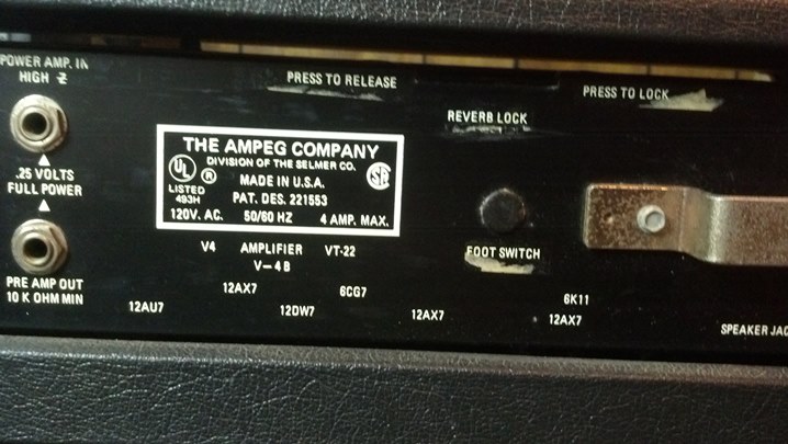 Magnavox owned both Selmer and Ampeg for a while, if I recall correctly. Note the tube layout information.
 Here is the other bracket for the cord, and the output jacks and impedance switching.
 Dude, are you still smoking?
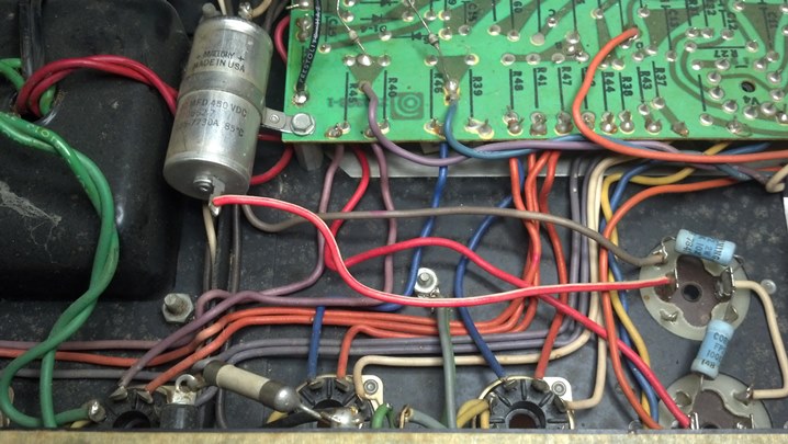 This is a nice intersection between hand wiring and the use of an etched circuit board.
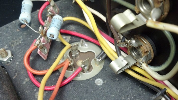 This cap and the bleeder resistors are slated for replacement.
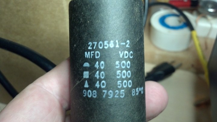 Yes, you can still get multi-section capacitors if you shop diligently.
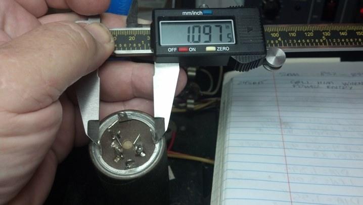 The prongs of the new capacitor need to fit in the slots in the chassis.
 There is plenty of height inside the chassis, but it doesn’t hurt to document what we have.
 Likewise, we’re documenting what we have.
 Here is the new multi-sectioned filter capacitor and the hole where it goes in the background.
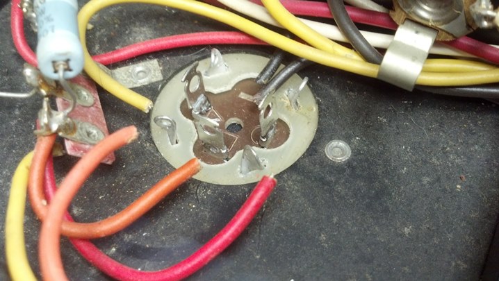 The outer can of all of the capacitors is isolated from the chassis, so these green fiberglass spacers are used under the capacitor.
 I think we’re done here!
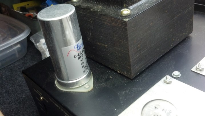 The new cap looks nice on the top of the chassis.
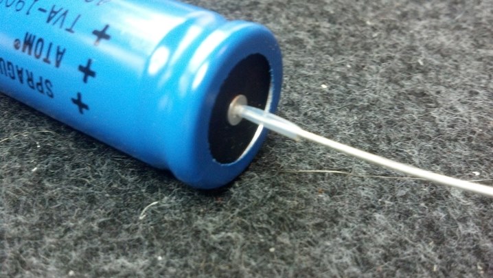 The axial filter capacitor will be replaced with this part. I am forming the leads to appear in a manner similar to the original part, seen above. A little Teflon insulating tubing helps keep the electricity under control.
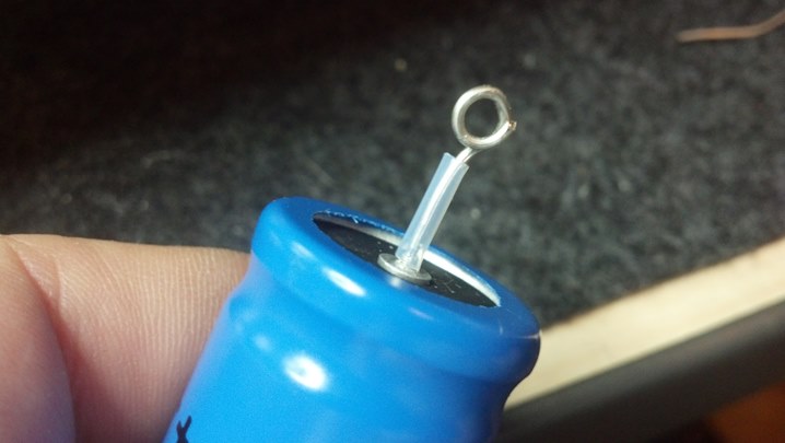 Wires will be attached to the terminals, so the leads are formed into a loop to accept the wires.
 The wire bending is done with a hand-tool called “chain nose pliers.”
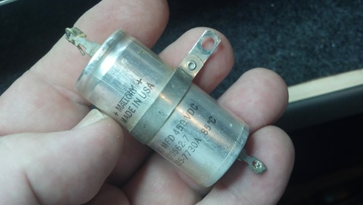 The original part has a mounting ring around it. We will need to recycle this mounting scheme to maintain originality.
 The ring is off! I was a little concerned that I would mess it up, but a little heat was all it took.
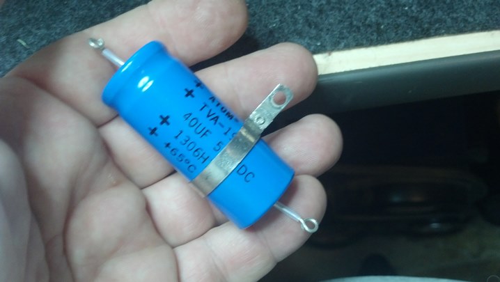 Here is the original mounting ring applied to the new capacitor.
 The ring can slide around just a little bit to give us a nice-looking mounting solution.
 And here we are, all wired up and ready to go back to work.
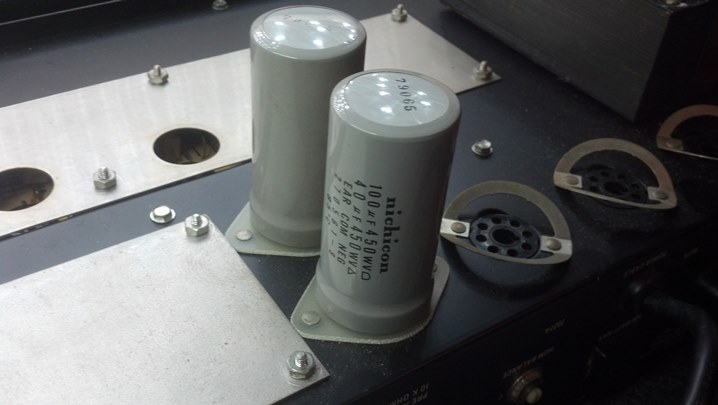 These guys have been replaced recently, and they check out as new. So, they will remain in service.
 Some of the front panel slide switches were dirty, so some cleaner and lubricant were sprayed into them.
 Now that the caps are changed out, let’s look at the top of the chassis. The output transformer and output tubes are on the left side of the chassis.
 The preamp tubes and power transformer are at the right end of the chassis.
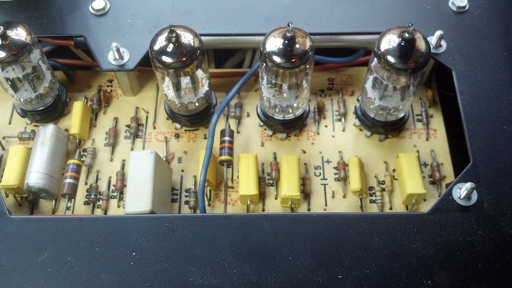 The open areas around the tube sockets are a nice touch. The chassis is steel and very stiff, even with the relief.
 More low and medium voltage goodness at the other end of the slot. Nearly every schematic test point is accessible from the top of the unit without turning it over on the bench.
 This 6K11 Compactron tube tests very good, with each of the sections closely matched to the others. Good News!
 The input jacks were corroded, so these were changed out with new Amphenol units.
 Here is the inside-the-chassis view of the new jacks.
 The neon indicator for the AC power was functional, but the indicator for the high voltage was not.
 So, this neon indicator will take its place. The mounting hole is the same size, but the new part is chrome. What to do?
 We scrubbed the chrome ring with steel wool, then applied several coats of black polyurethane paint to the bezel.
 Here are both indicators. The high voltage is amber, and the AC indicator is red, as it was when the amp came from the factory. The colors are a bit messed-up because of the jpeg processing in the camera… looks good in Real Life!
 Another happy customer picks up his finished bass head!


