Gibson C-0 Classical Guitar Fret Dress

An interesting tool came in the mail from the good folks at Grizzly Tools. This file is polished smooth, with two quarter-round concave file surfaces on opposing corners. It can be used as an alternative to the traditional fret dressing file. Let’s try it out on my 1968 Gibson C-0 classical guitar, that was cleaned up in an earlier post but could still benefit from a thorough fret dressing.  (Photo courtesy of Stewart McDonald.)

I’ve recently added a leather sandbag to my luthiere tool set. The little bunny ears really hold the neck securely. NOTE: Be Aware that this bag is sold as a rest for use at the gun range, but makes an awesome neck support.

The mat is a section of a floor covering used in gyms.  These mats are often used underneath workout machines and in the free weight areas.  They are tough and plenty cushy, just the thing for your luthier’s workbench.  And one mat can be slit into enough pieces to outfit four or five guitar workstations.

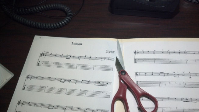
I covered the sound board with a sheet of corrugated cardboard. No sense in risking any damage to that fifty-year-old piece of cedar!  A pair of heavy-duty scissors is barely adequate for the job.

So here’s the cardboard sound board cover at work.  This will keep stuff out of the sound hole as well as help prevent gouging the guitar.

The frets are leveled with emery paper glued to this straight edge.

Here we are going to work with the new file. The file works best with the wide part of the blade vertical to the fret board when going along the length of the fret wire.  You can see a little black magic marker on the tops of each fret wire, which serves as a visual indicator on where (and where not) to remove material.

With this file, I did not feel it was necessary to tape off the fret board because the filed particles were not small enough to lodge in the grain of the rosewood. Also, the thickness of a layer of tape would have held the blade of the file away from the corners of the fret wire ends that needed to be dressed. The fret wires were very smooth after the filing was complete, so the fret polishing was almost trivial.

The creation of this saddle was documented in an earlier post. We’re ready to restring!

I can say that these strings are excellent! They are just a tiny bit smaller in diameter than the Augustine strings I had been using, and no intonation problems. These are a keeper!

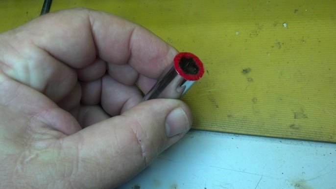
Some customers wanted more pictures of how I tie off the classical guitar strings at the bridge tie block. Note that the ends of each string is tied underneath the loop of the string next to it.  I start at string one (high E) and then secure the end in the loop of the next lower string.  This looks neat and really assures me that the knot will not come loose and the string come untied.

Here, I’m taking my time to show how the last string (string six or low E) is tied off.  The direction of the wrap forming the loop is in the opposite direction of the wrap used on the higher strings.  This causes the free end of the E string to ‘point’ in the direction of the A string, in whose loop it shall be secured.

Now the knots in both strings are pulled tight. You can now see how the A string really holds everything in place.  The end of the A string projects through the loop of string six (the low E.)  We’re done here.

As I work on this guitar more and more, it gets better and better. These new strings sound wonderful. Leveling and dressing the frets make every note crisp and clean all the way up and down the fret board. The Grizzly fret file is a keeper!

Thanks for reading all the way to the end!


CONTACT: David Latchaw EE

281-636-8626

Fender Bassman LTD Tweed Factory Workmanship Problems

This beautiful reproduction amp worked well for a while, then began to exhibit strange symptoms. After quitting entirely, the owner called the Unbrokenstring Crew.   Can we fix it?  Yes we can!

At first glance, this amp looks to be a chip off the old block. Other than the label on the back and the like-new condition, this amp is almost indistinguishable from the original model.

The lovely control panel lends a little mirror-like bling to the case.

WARNING: Tech porn. My, aren’t we starting early in the post with the porn?

The chrome faceplate shows every fingerprint.  This will need to be polished before the owner gets his amp back.

The silkscreen is a little worn off the nameplate but the chassis model is intact.

You can clearly tell that the cabinet is pine and not plywood nor MDF board.

WARNING – More Tech Porn – If you turn up the sound, you can hear some heavy breathing! Let’s fix this!

The rear panel is lined with aluminum tape.  The green wire grounds the foil to the rest of the chassis.

Here we see the hand-wired tube sockets.  Although I would like to have seen the control panel hand wired as well, this is overall the best way to build a tube amp, IMHO.  The dangling green wire is the ground wire to the foil seen in the previous picture.

The chassis wiring is a combination of wire-to-board and wire to flag terminals.  Two printed circuit boards are employed; one for the components in the amplifier itself and another one for the front panel control wiring.  Also note that the loudspeakers say “SPECIAL DESIGN.”  I’ll explain what that means later.

Here we see the input jacks and preamp tubes.  Sorry about the glare in the pics.

Let’s get that circuit board out, because I found a bad connection that requires solder rework.  The input jacks are already loose in this picture.

The nuts on the controls are called ‘small outline’ which is a nice touch that Fender added.  The small outline nuts will not show when the chicken-head knobs are installed.  Off they come!

Some sound came out of the loudspeaker when tapping around this area. What do you think we will find?

The stripped part of this wire may have been soldered at one time, but the solder joint failed. This wire pulled right out with nary a tug.

This grey wire also came out.  We need to remove this circuit board in order to do some serious work on the solder side.

There are about twenty five flag terminals with wires on them that need to be removed in order to pull the circuit board out of the chassis. Each wire is marked with nomenclature that matches the identification information on the circuit board silkscreen. Here, I’m making numbers with my Brother label machine.

Each number was repeated so that the label could be read from either direction. Here, the label is formed into a flag and looped around the wire.

As I moved the wiring around to free the circuit boards, more wires came loose. I speculate that the lead-free soldering was performed at the wrong temperature or with a flux that did not allow the strands of the wires to be adequately tinned while the joint was formed. Over time, these failed.

Each failed solder joint was re-flowed with real tin/lead solder using activated rosin flux. This rosin flux is not conductive, but the dust it attracts is conductive. Rather than take a chance with future problems (and to keep my workmanship looking nice) the circuit board is manually de-fluxed.

There. That’s better. This is what the solder-side of this board should have looked like when it left the factory.

And now it’s time to put this amp back together. This is where all those wire flag markers come in handy.

Yes, REALLY handy.  There are a lot of connections to be restored and I would have had some issues had I not marked each one with a flag.

The amp is back up and running. Here’s a pic of the bias check. Can you see how many milliamps flows through the tube pair at idle?

Here’s a pic of our favorite green wire, seen in an earlier photograph!

One of the screws would not tighten, so here you can see that I’m blowing out the debris from the hole prior to plugging it and drilling the plug to hold the cabinet screw securely.

All done. Do you remember that I mentioned something about those ‘Special Design’ loudspeakers? Well, if you ever want to replace these loudspeakers with other units, Be Aware that the magnets on those new speakers will hit the amplifier chassis. Be very careful to replace these loudspeakers with ones that will mechanically fit. Just sayin…

Thanks for reading all the way to the bottom!

CONTACT : David Latchaw EE
281-636-8626

K and K Sound Preamp in a Road Case

The owner’s classical guitar was instrumented with a piezo pickup at the saddle and a condenser microphone inside the sound hole of her classical guitar. Both signals are sent out of the guitar on a TRS cable to this two-channel preamp.

The Unbroken String Crew was asked if we could house this in a box of some sort that could be transported from studio to live venue in a road case.  A rack case was way too big.  Could we help?  The Unbroken String Crew says YES!

02 effects proc

Along for the ride is this processor which provides reverb for one of the channels coming from the preamp.

03 spanner screw

To fasten the preamp to a rack shelf, these little spanner screws will need to be removed and reinstalled. No problem, with the right tool.  Perhaps K&K wished to keep prying eyes out, but this will not hinder the Unbroken String Crew!

04 inside view 1

WARNING – Tech Porn.  The inside of the preamp is clean, a single-sided circuit board with only a few insulated jumpers on the bottom.  No surface mount parts here.  The strong point of this package is that the entire thing is surrounded with iron, just the thing to keep interference out of the high-gain, low-level circuitry found here.

05 inside view 2

WARNING – More Tech Porn. The 4558 is a workhorse amplifier, often found in high fidelity circuits.

06 inside view 3

WARNING – Yet More Tech Porn. The TL074 is another mature, well-behaved amplifier.

07 rack shelf

This rack shelf was cut down and re-purposed for service as a method to facilitate mounting the preamp on a 1U space without treating it as a traditional half-space unit. The preamp will look better centered in the rack space.

08 trial fit

The trial fit looks pretty good!

09 no feet

The rubber mounting feet on the bottom of the preamp need to come off.  They are press-and-stick, so we can peel-and-discard them.

10 ground bolt

The ground stud in the middle of the circuit board goes all the way through the bottom of the case.  We can use this as one of the mounting points, securing the preamp to the shelf.

11 preamp ready

Everything is bolted down, including the two side ‘wings’ that keep fingers out of the electronics.

12 start stack

This is a mock-up of the units that will be fitted into the rack rails.

13 rails and fillers

This is the operator’s view of the front of the unit.  Everything, including some blank panels, are bolted to the 5U rack rails

14 bracket prep

The corners of the unit will be fabricated from this two inch aluminum channel.  Here, we’re tapping a hole for 1/4-20 hardware that will be used throughout.

15 rail assembly

The front and back rack rails on one side of the unit are screwed to the aluminum corners.

16 guts

Both end assemblies are bolted to the equipment.  Can you visualize how this comes together?

17 wood ends

Each end is covered with Baltic birch plywood.  These furniture screws bolt the plywood cover to the end assemblies.

18 with top

We’ve installed the top onto the end assemblies.  A 1U rack space was left above the preamp because the nomenclature for the control knobs is printed on the top of the preamp, which would be obscured by the top if the preamp was installed in the top slot or if a blank filler panel were installed above the preamp.  There is also a LINE/MIC control for one channel that is only accessible from the back, but the customer would almost never need that feature.

19 panel fab1

The back panel is fabricated from a 5U blank panel.  Holes for the electrical connectors and the power outlet are bored.

20 panel fab2

The mounting hardware screw holes are placed as required.

21 panel fab 3

Here you can see the IEC power socket.  The line-level outputs are XLR/TRS bulkhead connectors from Neutrik.

22 panel fab 4

Shielded twisted pair wire is attached to the back of the connectors and are strain-relieved.  The TRS input jack that accepts the cable from the guitar is located on the far right of this picture.

23 first test

Now we did a test run to verify functionality and then off to the studio for our first real music!  Powered speakers are the load.  There is a guitar here somewhere, but it is not in the picture…  email me if you find it.

24 straight edges

Now that we know this all works, it’s time to finish the raw edges.  We’ll sand them straight to remove the saw marks.  This emery paper-covered Stanley level is also used to level fret wires.

25 edge finish

Self-adhesive oak edging is used to cover the exposed edges of the birch plywood.

26 trim

The edging is trimmed flush with the plywood with a sharp Exact-o knife.

27 sealer drying

The wood parts are saturated with MinWax Wood Hardener, which is just a shellac wash.  Coat after coat is applied until the wood is saturated and sealed.

28 base fit

This bottom is fabricated to fit into the road case.  The road case is an off-the-shelf case for a Mesa Boogie Quad Rectifier amplifier head.

29 base

This is a good fit into the foam, but it is not tight.  The unit can be removed from the base of the road case as needed.

30 Final Assy

The partially-disassembled unit is lined up on the base and the holes are marked for the furniture screws that fasted the unit down to the base.

31 power cord

The power cord can be left in place during transport if I carve away this little bit of foam.  There is plenty of space left in the road case for cords and cables to be stored with the top of the case in place.

32 All Done

This is the assembled case.  The preamp will now be installed, the top of the road case latched down, and this guy is ready to travel the world!  We may come back later to paint the wood black, because the new owner complained that this unit distracted peoples’ attention from the musicians!  We can’t have that!

You can hear this box at work (and listen to an awesome ensemble as well) here: http://www.paranamusic.com/


Thanks for reading all the way to the bottom!

CONTACT – David Latchaw EE
281-636-8626

Taming Your Sheet Music

From time to time, my students has problems with single sheets of musical staff paper blowing off their music stands.  So, the Unbroken String Crew came up with this solution:

SheetMusic1

We grabbed a manila folder and placed the sheet music on the folder.

SheetMusic3

Note that the sheets are almost as large as the manila folders.

SheetMusic2So, with a pair of scissors, we trimmed off the margin around the music staff.

SheetMusic4Now that the margins are trimmed, we have some space for some invisible tape.

SheetMusic5We position the sheets so that the edges are well away from the edge of the manila folder.  Can you see the invisible tape?  I can’t either.

SheetMusic6Sheet music that covers only two pages can be taped inside the manila folder.  For scores that exceed two pages, another manila folder is cut apart to make an inside page ‘carrier.’

SheetMusic7Here, both sides of the cut-down manila folder inner page are used to hold sheet music.

SheetMusic8

And would you believe, the whole thing can be folded shut and stored in a file cabinet?  And the title and composer info can go on the tab?  Who would have thought?

Sometimes the simple solution is the best solution.  As we sometimes play outside, or in front of fans, single sheets of paper are Bad News.  This little trick weighs down each sheet and keeps it flat.

Thanks for reading all the way to the bottom!

CONTACT: David Latchaw EE

281-636-8626

Fender Princeton Chorus Input Jacks

01 The Patient

This solid-state Fender Princeton Chorus is an awesome little amp, but the input jacks were worn out.  A call came into the Galactic Headquarters of Unbrokenstring.  Could we help?  Yes we can!

02 Rear Panel TextThis unit was actually made in the USA, and the city of Los Angeles has duplicated the work of UL/CSA, for a fee, of course.  Is this a great country or what?  Let’s get to work!

03 Reverb Tank

I took a picture to document where the RCA plugs on the spring reverb tank belonged when it came time to reassemble the unit.  My memory isn’t what it used to be.

04 QC Sticker

Nice to see that someone cared at one time.

05 LoudspeakersSeparate cable pairs come out of the chassis for each loudspeaker.  Nobody has touched this in a while!

06 Broken Input JacksToday’s mission objective is to fix this.  You can read my earlier rants about plastic input jacks and international safety approvals.  But, to keep this amp original, we will go back with the authentic Fender part.

07 Chassis on the Bench01Here’s the amp on the bench.  WARNING: Tech Porn To Follow

09 Chassis InteriorThis top view shows the usual single-sided circuit board found in a lot of consumer gear.  This amp is pretty clean inside!

12 Knobs

Get your knobs off.

10 Felt on SocketSome folks have asked about the felt-covered sockets I use.  Here is a closer picture of the one I will use on this faceplate.  The faces of a set of sockets is ground flat on a bench grinder.  A square scrap of felt from the fabric department is super-glued to the ground face.  When the glue is dry, an Exacto knife liberates any felt that is not glued to the socket itself.

11 Control Nuts Coming OffA little automation goes a long way.  This little low-rpm driver keeps the carpal tunnel problems away.

13 Closeup of Broken JackCompare the old jack on the left with the new jack on the right.

14 Another Happy CustomerThe reassembly is the reverse of the assembly.  Another happy customer picks up his amp!

Thanks for reading all the way to the bottom!

CONTACT INFORMATION:

David Latchaw EE

281-636-8626