This powered monitor/PA box was badly abused but could become the basis for a good keyboard amp. Could the Unbrokenstring Crew put it back together and make it gig-worthy?
 All of the parts are here, but they are rattling around inside. Electrically, it worked, but the third-world construction techniques rendered the unit worthless for loading in and out of a venue.
 For instance, the control panel was literally kicked inside the enclosure. Yes, those are wood brads fired from a nail gun.
 The trim plate was easily removed.
 To get a good look inside, the main loudspeaker was removed.
 There are all kinds of things rattling around inside this unit.
 The horn driver is shot. Proceeding with exploratory surgery, the lens is coming out.
 This driver is threaded, which implies that if it needs to be replaced, a standard compression driver can be selected.
 This driver is probably a Chinese copy of a Motorola unit. The series resistor is all this unit has for a crossover network.
 Disassembling the driver reveals this one-inch cone.
 Behind the cone is this piezo driver. It has come loose from its mounting and one of the connecting leads is broken.
 The piezo element was glued on to the back of the cone. This is some fine Far East engineering!
 The resistor in series with the compression driver has miraculously survived the abuse.
 I am a big fan of these compression drivers. They are low-cost, covered by a warranty, and compatible with this setup.
 In this application, it is an equal or better replacement for the plastic driver that we are removing.
 These crimp-terminals are handy, although we may use some insulated ones that are the same size.
 This crossover network is compatible with the new compression driver and loudspeaker, plus it is adequately sized for the power levels involved.
 The only weakness out-of-the-box is that the large inductor needs additional support, particularly if this crossover network is installed in gear that will be loaded out for gigs. The shiny glue is actually hide glue.
 Here is the crossover network in its new home. The main power transformer is on the left and the power amp with the large black heat sink is on the right.
 Shifting out attention to the user interface, the control panel is separated from the piece of MDF board.
 A quick inspection of the power amp reveals that it is functional. However, temperature cycling and vibration have broken a couple of solder joints. These will be repaired before returning the circuit board to service.
 I tried to drive the brads out of the MDF the same direction that they were driven in. However, they were VERY firmly stuck in the wood.
 I decided to just trim them flush and get on with the process.
 This black marker is adequate to disguise any exposed MDF around the control panel.
 This piece of MDF will be glued and screwed in place from the inside of the cabinet. Here we are pre-drilling the MDF to prevent the screws from splitting the thin material.
 These screws will be driven from inside the cabinet.
 Oh, look here! More stuff rattling around inside the cabinet!
 I wonder where this goes?
 The control panel is about ready to reinstall.
 A little glue is spread around the inside of the main cabinet where the control panel will be fastened.
 The control panel goes here.
 A socket wrench drives the bit, seating the screws. Not much room here for a powered driver.
 This is another view of the control panel mounting scheme and the 100 watt amplifier.
 The AC power for the amplifier is filtered by the yellow across-the-line capacitor seen on its own circuit board.
 Time to start putting things together for real.
 We’re drilling a hole to mount an L-pad attenuator that allows the user to set the level of high frequency audio coming out of the horn. The fixed resistor seen above will be eliminated by this L-pad.
 The L-pad level control looks almost factory.
 The main loudspeaker seems OK.
 Some closed-cell foam is installed around the loudspeaker to seal the cabinet. Peeling the white paper backing reveals an adhesive back that keeps the foam in place.
 More foam is used to seal the space around the horn lens.
 I might drop something down inside the horn lens while working with this unit, so I stuffed a rag in the lens to catch whatever I might drop.
 The edge of the horn driver magnet just touches the back of the control panel circuit board. Oops.
 A durable insulator was fabricated from a bit of junk mail.
 Now, this thing is LOUD! We shall declare this bit of reconstructive surgery a success!
Thanks for reading all the way to the end!
CONTACT – David Latchaw EE
281-636-8626

 This unit has a 1U rack space under the head unit, which is a nice touch!
 Let’s take a look around the inside of the unit. The power transformer and heat sink dominate the center of the unit.
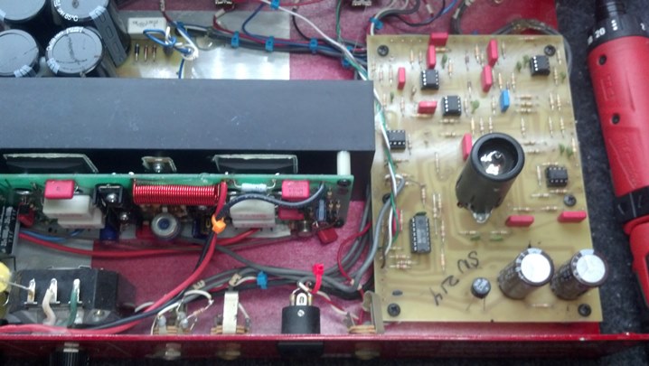 The preamp is hybrid solid state / hollow state.
 Looking at the rear of the front panel, we see the input jacks and equalization controls directly mounted and hand-wired to the circuit boards. Most of the work we need to do today is right here.
 The configuration switches are seen here. That big black block in the middle is the top of the heat sink.
 We see the fan here, which blows the length of the heat sink. The power transformer has a bit of tape and foam on it.
 Looking at the inside of the rear panel, we see the power jacks and fuses. Can you see the bridge rectifier?
 This big potentiometer dominates the rear panel, setting the line out level.
 From this angle, we can see a the filter capacitors. Electrically, this unit is very solid.
 Each control is rinsed out with some Blue Shower cleaner. The cleaner is applied from the rear of the potentiometer, rinsing the crud away from the resistive element.
 Then the control is dried with some compressed air in a can.
 This anti-corrosive cleaner/lubricant works well on the actual resistive element and wiper.
 This synthetic lubricant is just the ticket for lubricating the shaft.
 After reassembly, the unit is checked out. Note the ease by which the loudspeakers are connected to the head unit.
 This unit is now fully functional, with no more control noise. Back together it goes!


