This five watt head had gone nearly silent. The national retail chain that sold it told the owner to purchase a new one, because that’s their business model. Could the Unbrokenstring Crew repair this unit and bring it back to life?
 At five watts, this head is bedroom-friendly, yet there are plenty of opportunities for distortion and tone shaping.
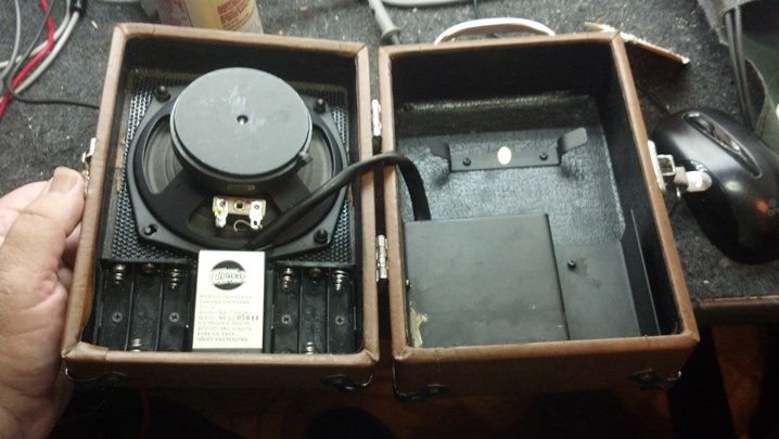
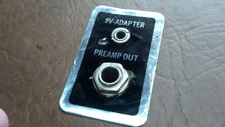
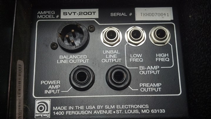
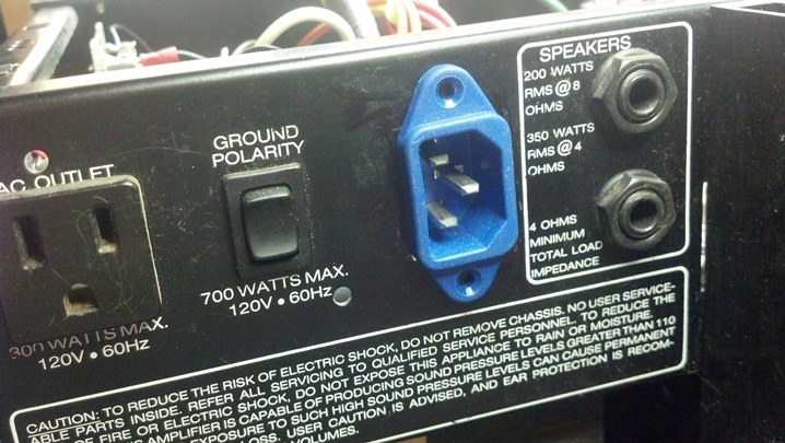
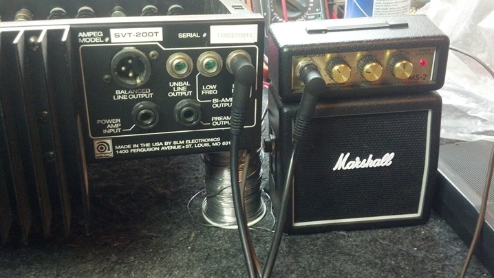
 Interestingly, there are three options for outboard speaker cabinets as well as all of the usual in’s and out’s.
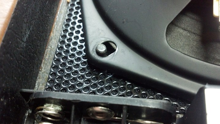
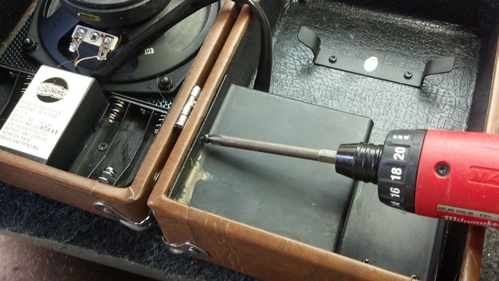
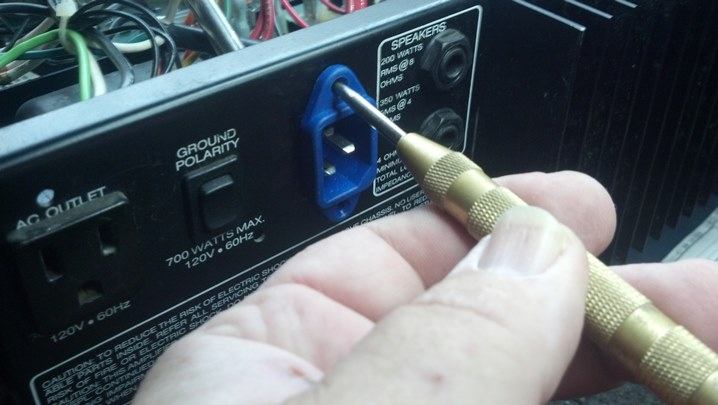
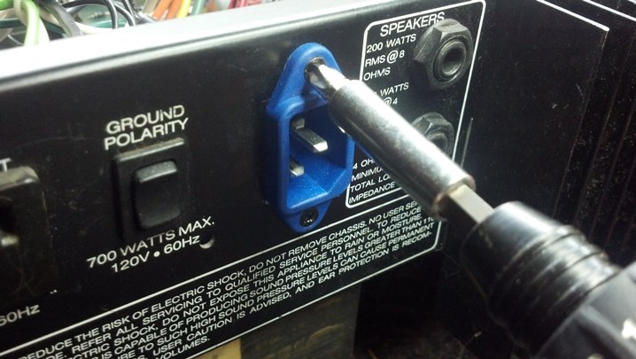
 The back comes off with these screws. But it appears to be stuck in place!
 I speculate that when the unit was built, the Tolex glue was still fluid and squeezed out between the back and the frame, sticking the rear cover in place.
 The chassis is held in with these screws. No surprises here.
 This is a hybrid solid state / tube unit, with a 12AX7 triode pair in the preamp section and a dual triode 12BH7 pressed into service as a push-pull tube output stage.
 There are two different versions of the schematic available. They can be easily identified by checking the number of conductors in that big ribbon cable that connects the rear panel circuit board to the main circuit board. This particular unit uses the cable with 21 conductors. Thanks to Armando Garcia at Mars Electronics who furnished this schematic!
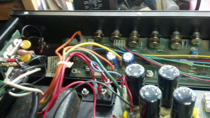
 In the foreground are the big heat sinks for the voltage regulators. The rear panel wiring board is in the background.
 Viewed from the other side, the main circuit board contains the preamp circuitry.
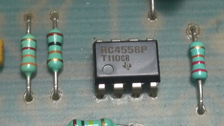
 The preamp uses DSP techniques to create the reverb effect and the tone-shaping functions of this unit.
 This is the preamp tube. It’s fine.
 This is the 5 watt output tube.
 This part checked OK but it is a little weak. We will continue to use this unit for troubleshooting purposes.
 This is the pin-straightener from my tube tester. The Chinese tubes have a little larger envelope than the JAN versions of these tubes, so the tube is a tight fit in the straightener. If the tube envelope is too large, the pins can be straightened using the same tool, but the pins are inserted from the other side of the straightener.
 So the output drive signal is split into an in-phase and out-of-phase copy, and applied to the grid of the output tube. But the plates of the 12BH7 are stuck at +300 volts.
 The primary windings of this output transformer are shorted to each other.
 Let’s get this transformer off the chassis and take a closer look at it.
 These Chinese transformers are usually not worth fixing, but this transformer is hard to find. Some exploratory surgery shows us that the problem is deeper in the windings and not readily repairable.
 So, out it comes entirely. The search is on for a replacement. The original manufacturer has no stock.
 Hammond makes a versatile aftermarket unit that is available through distribution. We can make this work!
 The frame of the transformer is just a little bit larger than the original part. One of the mounting holes is being moved.
 Placing the magnet near the site where the drill is working helps keep those pesky metal shavings under control.
 The new transformer is bolted in place and some Thread Locker is applied to the bolts to keep it in place.
 Here the output leads are threaded through the insulating grommet in the chassis.
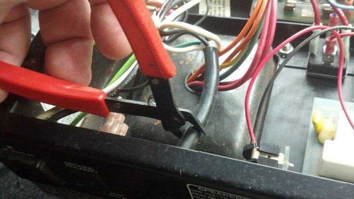
 The input wiring is soldered into place, so the leads are trimmed to length.
 To preserve the original wire insulation colors silkscreened on the circuit board, short pieces of the original wiring were left in place and butt-spliced to the new output transformer harness.
 This unit is ready to test. Pretty neat looking!
 Surprisingly, this unit has a bias pot and a balance pot. However, there is no commonly-available information available for the technician to set these. So, I wrote this procedure:
BALANCE ADJUSTMENT
- Set DMM to mV range
- Affix DMM probes to TP6 and TP7
- Switch POWER ON; switch STANDBY ON after five minute warmup.
- Adjust BALANCE pot for 0V display on DVM
- Switch all power OFF
BIAS ADJUSTMENT
- Affix black DMM lead to ZD2 cathode (banded end) near Input Jack. This is a convenient GND.
- Affix red DMM lead to D20 anode (not banded end.)
- Switch POWER ON; switch STANDBY ON after five minute warmup.
- Adjust BIAS pot so that DMM display is 46mV. This puts about 10mA of idle current through the 12BH7.
Recheck BALANCE and BIAS adjustments as they are slightly interactive, particularly if the internal sections of the 12BH7 tube are not matched. Follow all the usual precautions of removing power and working safely around high voltage!
Thanks for reading all the way to the end!
CONTACT – David Latchaw EE
281-636-8626

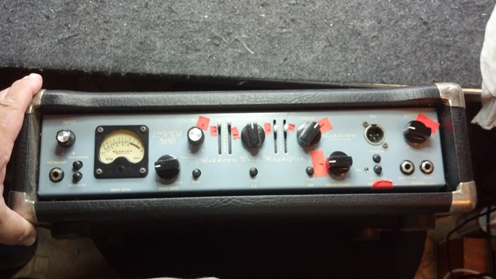
 A quick scan of the front panel shows that the input circuit sports the sort of flexibility that the Peavey Marketing Department loves to explain to anyone who would listen…
 Each channel has independent gain, and a master volume to Rule Them All. Effects can be inserted via the front panel.
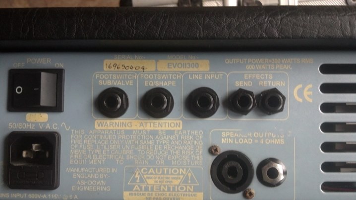
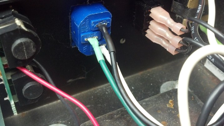
 On the rear panel, we have parallel speaker jacks and the usual ground/no-ground power switching. Peavey often married different front panels, which contained preamp circuitry, to different rear panels, which carried power and audio amplifier components. The ‘series’ number goes with the power amp, not the front panel. We Got This.
 Name, rank, and serial number, please.
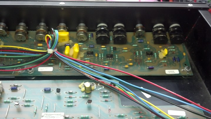
 Pulling the front panel, we see that all of the components are mounted on one circuit board.
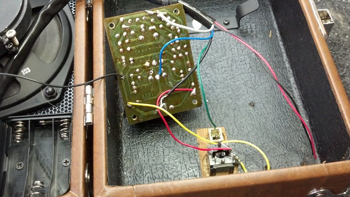
 I took a few pictures to be sure that the wiring and cables were returned to the same spot when we are through.
 The cable to the right is just wired to the power indicator. The other two carry signals.
 This is a better view (to be sure that they cables are properly oriented on their pins.
 The front panel is free of the rest of the unit.
 All of the controls and switches will be cleaned so this assembly comes completely apart.
 We can now clean and lubricate everything now.
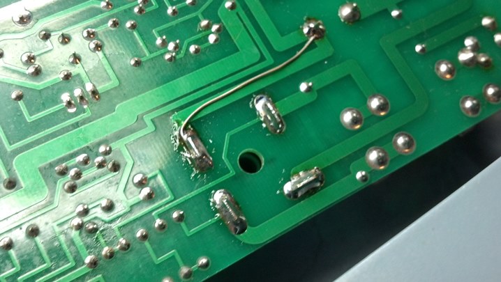
 Can you spot the broken solder joints?
 Someone has been here before! This needs to be cleaned up, too.
 The Blue Shower is a good cleaner. The DeoxIt contains a lubricant for the potentiometers. Good Stuff!
 Back Together it all goes!
 This screw hole was stripped out. First, we will soak the stripped hole in the wood with this wood hardener.
 Next, a birch dowel is cut to partially fill the hole. The dowel reduces the apparent diameter, allowing the screw to hold.
 With the stripped hole repaired, we are back in business!
 This unit plays very well, and all the controls and switches are Like New!