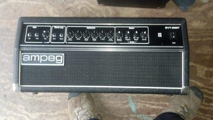
This wonderful old Selmer-era Ampeg bass head was pulled out of its retirement in the closet and put back into service. But it had a few issues to address, so that it could reliably pump out the tones that is the Ampeg Experience.
 This unit appears to be absolutely factory stock. The Houston humidity has had an effect on the aluminum faceplate.
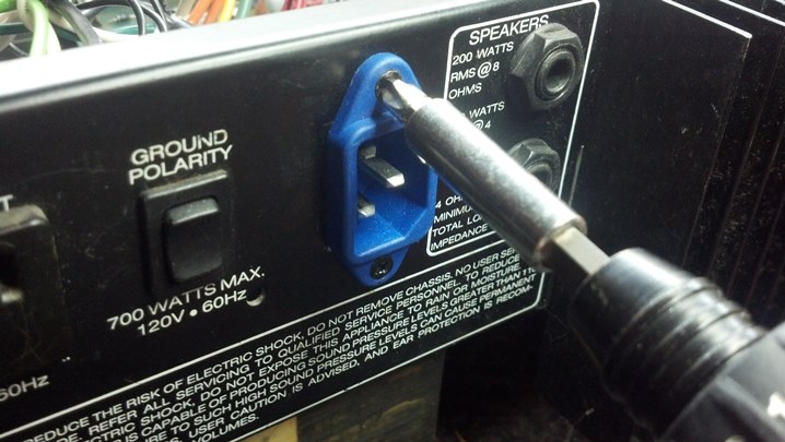
 Taking a tour of the rear panel, we see a bracket upon which the line cord may be wrapped.
 The convenience outlet is a three-prong unit, which is nice. The hum balance control adjusts the bias current in the output tubes to be the same.
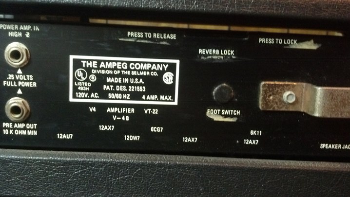 Magnavox owned both Selmer and Ampeg for a while, if I recall correctly. Note the tube layout information.
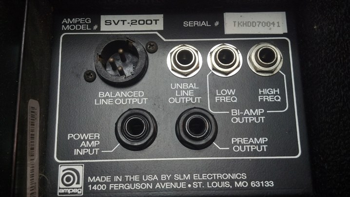
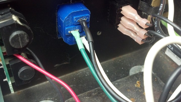
 Here is the other bracket for the cord, and the output jacks and impedance switching.
 Dude, are you still smoking?
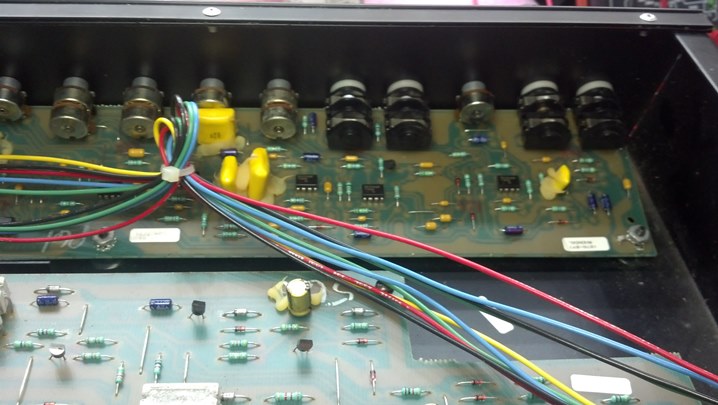
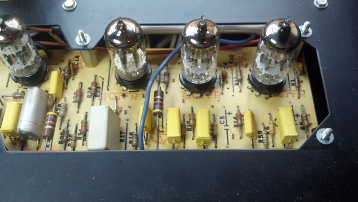
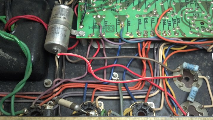 This is a nice intersection between hand wiring and the use of an etched circuit board.
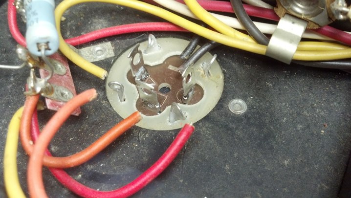
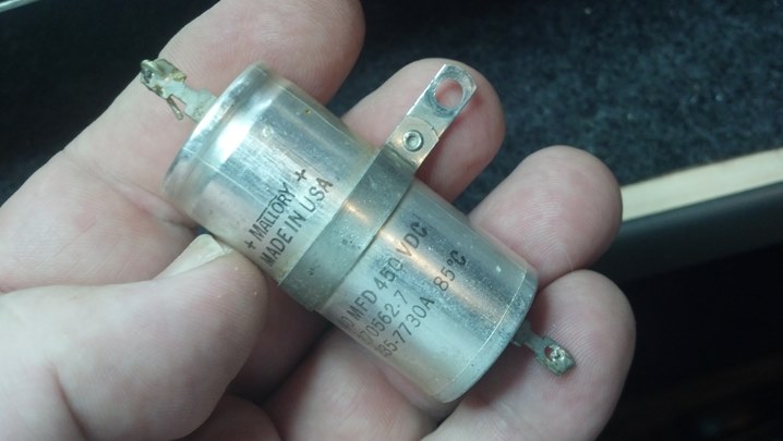
 This cap and the bleeder resistors are slated for replacement.
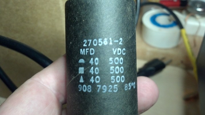 Yes, you can still get multi-section capacitors if you shop diligently.
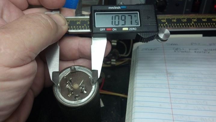 The prongs of the new capacitor need to fit in the slots in the chassis.
 There is plenty of height inside the chassis, but it doesn’t hurt to document what we have.
 Likewise, we’re documenting what we have.
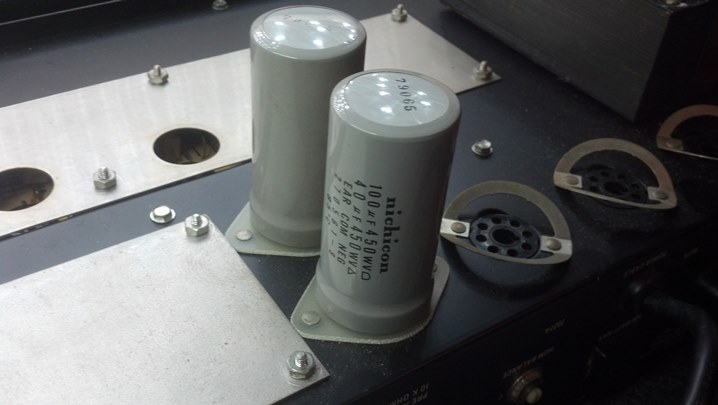
 Here is the new multi-sectioned filter capacitor and the hole where it goes in the background.
 The outer can of all of the capacitors is isolated from the chassis, so these green fiberglass spacers are used under the capacitor.
 I think we’re done here!
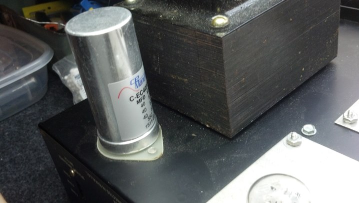 The new cap looks nice on the top of the chassis.
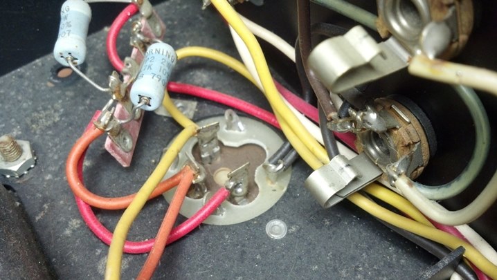
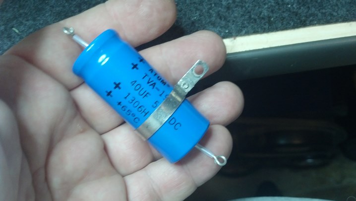
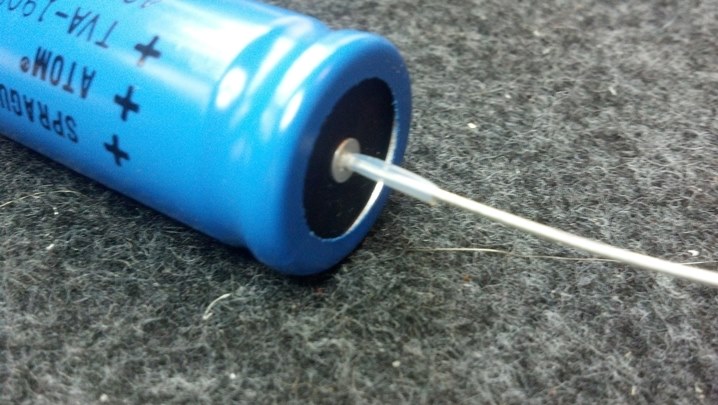 The axial filter capacitor will be replaced with this part. I am forming the leads to appear in a manner similar to the original part, seen above. A little Teflon insulating tubing helps keep the electricity under control.
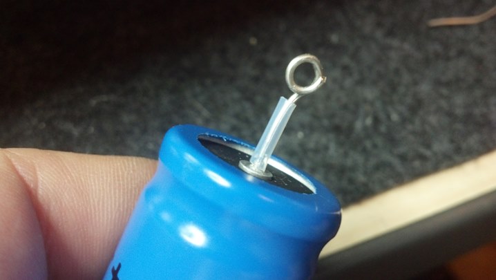 Wires will be attached to the terminals, so the leads are formed into a loop to accept the wires.
 The wire bending is done with a hand-tool called “chain nose pliers.”
 The original part has a mounting ring around it. We will need to recycle this mounting scheme to maintain originality.
 The ring is off! I was a little concerned that I would mess it up, but a little heat was all it took.
 Here is the original mounting ring applied to the new capacitor.
 The ring can slide around just a little bit to give us a nice-looking mounting solution.
 And here we are, all wired up and ready to go back to work.
 These guys have been replaced recently, and they check out as new. So, they will remain in service.
 Some of the front panel slide switches were dirty, so some cleaner and lubricant were sprayed into them.
 Now that the caps are changed out, let’s look at the top of the chassis. The output transformer and output tubes are on the left side of the chassis.
 The preamp tubes and power transformer are at the right end of the chassis.
 The open areas around the tube sockets are a nice touch. The chassis is steel and very stiff, even with the relief.
 More low and medium voltage goodness at the other end of the slot. Nearly every schematic test point is accessible from the top of the unit without turning it over on the bench.
 This 6K11 Compactron tube tests very good, with each of the sections closely matched to the others. Good News!
 The input jacks were corroded, so these were changed out with new Amphenol units.
 Here is the inside-the-chassis view of the new jacks.
 The neon indicator for the AC power was functional, but the indicator for the high voltage was not.
 So, this neon indicator will take its place. The mounting hole is the same size, but the new part is chrome. What to do?
 We scrubbed the chrome ring with steel wool, then applied several coats of black polyurethane paint to the bezel.
 Here are both indicators. The high voltage is amber, and the AC indicator is red, as it was when the amp came from the factory. The colors are a bit messed-up because of the jpeg processing in the camera… looks good in Real Life!
 Another happy customer picks up his finished bass head!
Thanks for reading all the way to the end!
CONTACT – David Latchaw EE
281-636-8626

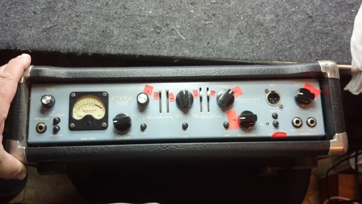
 This unit has a 1U rack space under the head unit, which is a nice touch!
 Let’s take a look around the inside of the unit. The power transformer and heat sink dominate the center of the unit.
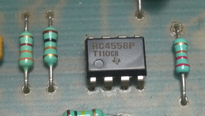
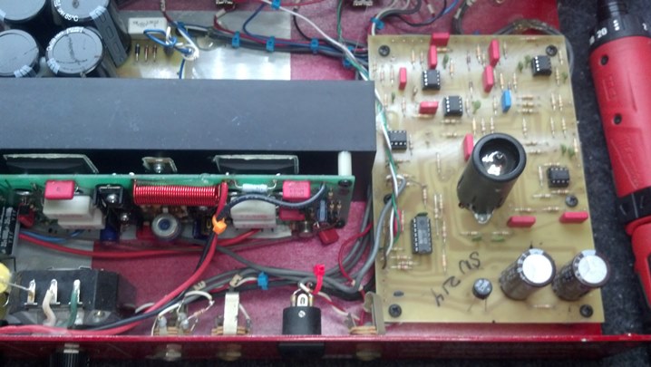 The preamp is hybrid solid state / hollow state.
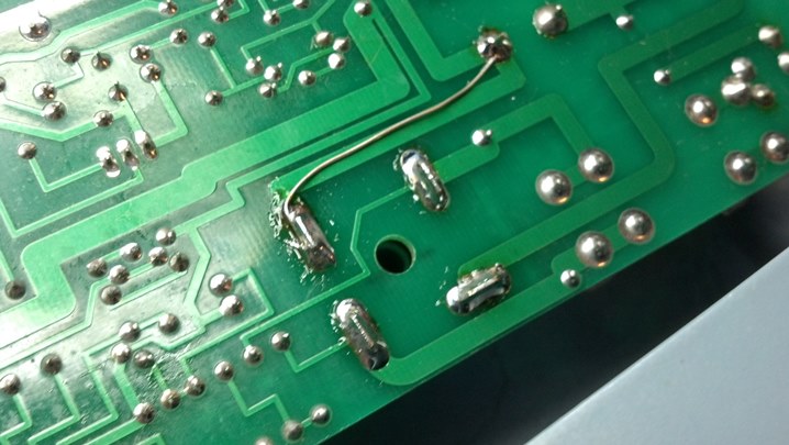
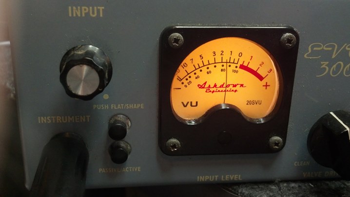
 Looking at the rear of the front panel, we see the input jacks and equalization controls directly mounted and hand-wired to the circuit boards. Most of the work we need to do today is right here.
 The configuration switches are seen here. That big black block in the middle is the top of the heat sink.
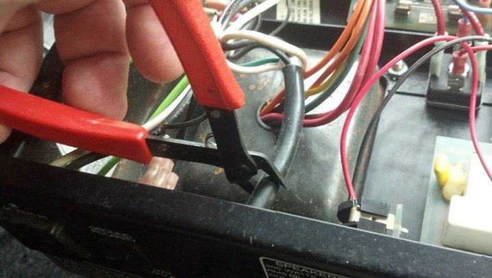
 We see the fan here, which blows the length of the heat sink. The power transformer has a bit of tape and foam on it.
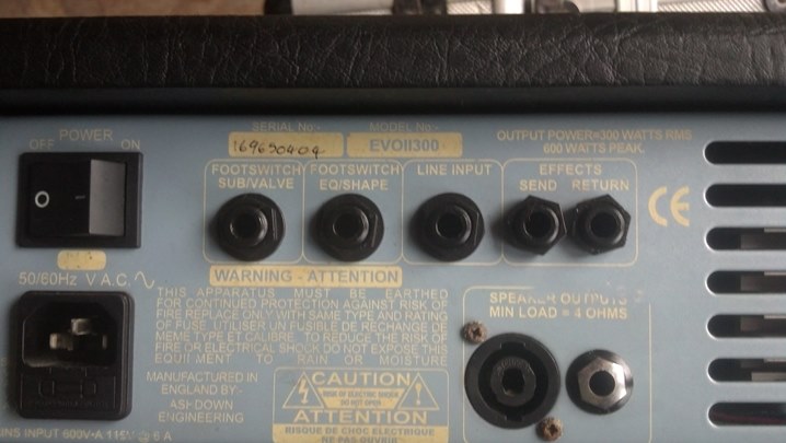
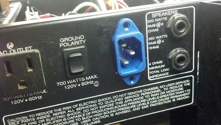
 Looking at the inside of the rear panel, we see the power jacks and fuses. Can you see the bridge rectifier?
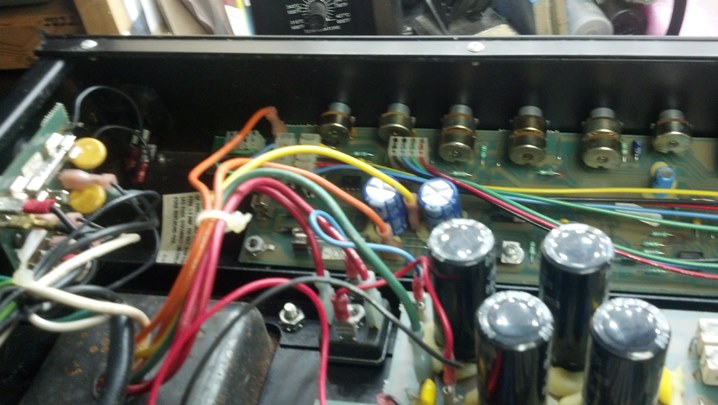
 This big potentiometer dominates the rear panel, setting the line out level.
 From this angle, we can see a the filter capacitors. Electrically, this unit is very solid.
 Each control is rinsed out with some Blue Shower cleaner. The cleaner is applied from the rear of the potentiometer, rinsing the crud away from the resistive element.
 Then the control is dried with some compressed air in a can.
 This anti-corrosive cleaner/lubricant works well on the actual resistive element and wiper.
 This synthetic lubricant is just the ticket for lubricating the shaft.
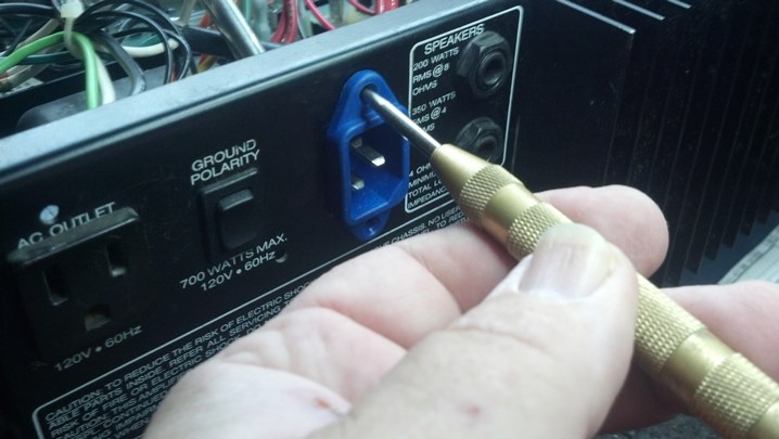
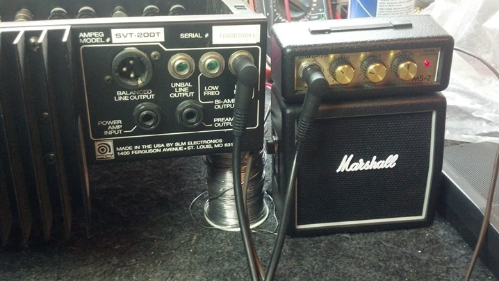
 After reassembly, the unit is checked out. Note the ease by which the loudspeakers are connected to the head unit.
 This unit is now fully functional, with no more control noise. Back together it goes!