St. Louis Music produced this handsome tube-based Crate amp. Robin said that this unit is ready for some service.
 I just love the blonde Tolex and clean appearance of this unit!
 The front panel reveals that this is a single input, two channel unit. The clean channel sports conventional treble and bass controls. Bringing the effects loop to the front panel is a nice touch! This jack is stereo, for in/out with one jack.
 The gain channel has separate gain and volume controls, and a mid-tone control.
 The foot switch is wired in parallel with the channel select switch seen above. Note the separate controls for reverb for each channel!
 These loudspeakers are original and still in great shape.
 Taking a tour of the bottom of the chassis, this unit has an attached line cord. The power transformer is affixed at an angle, as seen on the left. The grey wires go to and from the reverb tank.
 Five minutes of visual inspection is worth thirty minutes of troubleshooting. Can you see the problem?
 To remove the chassis, we need to unsolder the cables to the reverb tank. I marked this one so that it can be reinstalled in the proper place on the circuit board.
 The loudspeakers are wired in parallel. This pic documents the wiring colors.
 The chassis is now free of the cabinet. A quad of EL84 tubes serve as the class AB push-pull output circuit.
 The preamp tubes, in the foreground, and all 12AX7s.
 Removing the brackets on the output tubes is a little gnarly, though. This screw will be replaced.
 Silicone foam cushions the envelope of the tube from the stresses of vibration and thermal expansion.
 To do any soldering on the main circuit board, all the controls need to be disassembled. Marshall knobs, anyone?
 We have three jacks to disassemble in order to liberate the electronics.
 The primary and secondary wiring is easily disconnected from the circuit board, as shown here.
 One more chance: Do you see any electrical issues?
 We have the main circuit board well in hand.
 Some glue was used to support the large mechanical parts. This stuff needs to be chipped away.
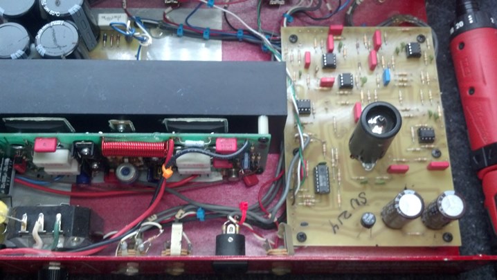
 Here, we are checking the caps in-circuit with the Heathkit capacitance checker, just to verify that they are toast.
 My only criticism of this amp (and others) is that the tube sockets are directly attached to the circuit board. The thermal expansion is more than the average solder joint can stand. Wire those sockets by hand; don’t mount on a PCB!
 Here we are with new capacitors. All of the solder joints have been inspected and reworked as required.
 With the unit disassembled, this is a good time to clean up and polish that gorgeous front panel.
 The wrong sized fuse was installed. The Unbrokenstring has a complete stock of fuses, for such a moment as this.
 Remember the broken screw? Here, we are drilling and tapping the chassis for a new screw.
 The blue masking tape was deployed on the inside of the chassis to catch all the metal shavings.
 The screw fix worked! As we knew it would.
 The reverb tank wires are fished back through the hole in the chassis and refastened.
 Everything has been reinstalled and we are ready to test.
 This cover conceals the bottom of the amplifier chassis. The amp was a little noisy. Could some shielding help?
 Aluminum foil tape is added to the cover. This will be electrically in contact with the chassis of the amplifier.
 Aluminum shielding goodness at its finest! This is all on the inside, so no one but you will ever know that it’s there.
 This Crate is very versatile – the clean channel is almost hifi quality, while the gain channel is a vast territory of sonic goodness to explore. And LOUD! Pick one of these up if you find one.
Thanks for reading all the way to the end!
CONTACT – David Latchaw EE
281-636-8626