Some Advice for Musicians Whose Gear Was Water-Damaged by Hurricane Harvey

Shortly after the Shuttle Explosion in 1986, the computers onboard the Challenger orbiter were retrieved from the floor of the Atlantic Ocean.  Each ‘set’ of boxes was sent to a different NASA Center for analysis.  One set came into the IBM Federal Systems lab in Clear Lake, Texas, where we dried, partially disassembled, and reassembled the hardware in hopes of recovering any clues regarding the accident.  I was the sub-contract manager at IBM at the time and was tasked with engineering support for the effort, including electrical test, micro-soldering, cable assembly, and such.  I am proud to report that the unit came back to life after two weeks of salt water immersion, and the data in the memory core was intact up to the point that vehicle power was lost; That information contributed greatly to the accident timeline.

So I want to weigh in on some strategies for musicians who found that their gear was water-damaged in Hurricane Harvey, which is still affecting Coastal Texas as I write this.  Let’s get going!

  1. Don’t turn anything on to see if it still works.  Odds are, it won’t.  And it won’t because you turned it on, dumbass.
  2. Unplug everything.  Your power is probably off anyway, but it never hurts to be sure.
  3. Remove ALL the batteries.  This includes tuners of all kinds, even the ones built into an acoustic guitar, guitar pedals and effect units, portable recorders, laptops, microphones, everything.  Same process as when your cell phone falls in the toilet.
  4. For all stringed instruments, slack the strings.  You don’t have to remove them, but just remove the tension.  Loosen the pegs on your violins/violas/cellos/basses to slack the strings; don’t bother with the fine tuners.
  5. For instruments with truss rods in the neck (guitars, basses, etc.) slack the truss rod.  Just a half a turn in the direction of ‘more loose, not more tight’ is the way to go.  For most instruments, that’s counter-clockwise.
  6. Drum heads on banjos and drum kits should be slacked as well, if the shell was wet.
  7. Many woodwinds will be OK if you were treating them with sweet oil on a regular basis.  The case will be in worse shape than the instrument.  Wipe everything with a dry towel and let it air dry for a week or two.  Inspect any pads and remove the reed; the reed will need to be replaced anyway unless you use synthetic reeds.

Now that everything is stable, let’s consider the recovery options.  The challenges we face are as follows:

  • Acoustic instruments made of wood are not damaged by a little water.  A lot of water will swell the wood and stress/break the glue bonds.  The sooner the liquid water is removed from the surface of the wood, the sooner we can begin the process of drying the instrument.  Wipe it down with a dry towel, inside and out.  There are instances of classical guitars stored in a basement in Central Europe that had absorbed TWICE THEIR WEIGHT in water that were successfully dried and returned to play-able condition.
  • Acoustic instruments made of wood ARE damaged by too much drying.  Shrinkage causes the wood to pull away from glue bonds and pull away from itself e.g. crack.  This Peavey neck became over-dried in hot attic:Fortunately, we have (and will continue to have) PLENTY of humidity so a good, slow, open-air drying over the next couple of weeks will cause the least damage to our acoustic instruments.  Resist the urge to pull out the hair dryer!
  • Solid body instruments are, more impervious to liquid water by virtue of the fact that they are usually finished in polyurethane or other rugged finish.  Again, wipe it down with a dry towel.  We’ll come back to work on the controls in a moment.
  • Martin guitars with the composite bodies, and Ovation guitars with their famous ‘bowls’ may be difficult to recover.  The sound board expands and shrinks at a different rate than the rest of the guitar.  Ovation will (upon request and sufficient $$) replace a wet top with a new one.  The Music Factory in Pearland has done this with a few of their new Ovations following the last hurricane.  I have not spoken with Martin but my guess is, you might have to call them and discuss the options.  Many of the composite/laminate guitars are under $500 which limits the range of repair options.

The areas of concern with our electronics fall into these categories: (1) cabinets and grille  (2) loudspeaker cones  (3) controls and switches.

Note that I did not say anything about the electronics themselves.  Electronic assemblies built after, say, about 1990, are mass produced by a process that uses water as a cleaning solvent.  This is called ‘aqueous cleanup’ and is almost ubiquitous in all electronic assembly shops around the world.  Your electronics will fare fare better in the flood than you think, particularly if we don’t energize them while wet.

  1. Let’s start on the cabinets and grilles.  Remove the grille and dry what you can with a towel.  The frame is almost always wood, and the fabric is almost always a synthetic.  The wood should be allowed to dry slowly over the next couple of weeks.  Do not apply any heat.  The frame may still warp a little, but we will deal with that when we reassemble the cab.
  2. Wipe all water from the cabinet, paying particular attention to the inside and bottom of the cabinet.  Remove the reverb tank, if it is present, and set aside.  Again, with the cabinet, a slow dry may be all it needs.  If the cabinet is made from particle board, you will see swelling which may spoil the appearance of the unit.  The particle board will never be as strong as it was before it got wet.  If your cabinet is particle board, you might convince yourself that Harvey has given you permission for an upgrade to a pine or plywood cabinet.
  3. Carefully remove any remaining liquid water from loudspeaker cones.  Let everything dry out for a week or two.  Then GENTLY push the cone evenly forward and back and listen for any rubbing or scratching noises.  If you don’t hear any noise (called ‘motor noise’) you may be OK.  Unfortunately, some magnets have a high concentration of metallic iron, which will rust (and swell) in the presence of moisture.  If the rusting is bad enough, the loudspeaker needs to be reconed or replaced.

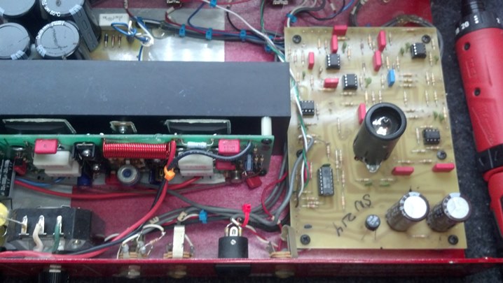
Let’s take a look at the electronics.  The controls and switches on guitars and the controls and switches on amplifiers are treated in a similar manner.  Circuit boards and wiring harnesses are not hard to clean up if you are handy.  If you are comfortable disassembling your amp head or accessory, then Read On.  If not, there are many shops (not just mine) that are on Facebook that are competent to perform these repairs.  I am detailing these procedures so that the do-it-yourself-er can have some confidence to proceed, and also so that the non-do-it-yourself-er can speak competently with your chosen tech.

  • Compressed air is your friend.  The air blast will remove any liquid water present.  After disassembling your gear, get compressed air underneath components, connectors, transformers, anywhere there is a place where water can reside.  Those little cans of ‘electronic dusters’ are cool but expensive.  Pull out the air compressor.  Pull the bottom plate off your pedals to gain access to anywhere water may be lurking.  Remove those pick guards and blow everything dry.  Open up those battery boxes (you did remove the batteries, didn’t you?)  Dry everything!
  • Switches need a rinse and then lubrication.  I use ‘Blue Shower’ as a rinse, which is for cleaning television tuners.  There are other products that work as well.  Google “CAIG” read up, and go shopping at Fry’s for some of the CAIG products they carry.  Start with the CAIG F5 stuff as a rinse, then the CAIG GOLD stuff as a protector lubricant.  I use the CAIG GOLD product as well as some MIL-SPEC stuff (because I Am Cooler than you and can get MIL-SPEC stuff and you can’t.)
  • Hit the input and output jacks with a little CAIG GOLD on a cotton swab.  This is just good routine maintenance, and is particularly vital now that your instrument may have been wet.
  • For controls that were working fine before the flood, I would just use a shot of the CAIG Fader Lube (same aisle at Fry’s) as a water displacer and a lubricant.  Don’t try to rinse good controls because you may displace the factory lubricant and put it where it may create noise on the resistive element.  Keep It Simple.
  • Cables may be problematic.  My advice would be to toss the wet ones and get new ones.  My reasoning is this: Cables are often the weak link in any setup, even when new.  You know this.  Water will deteriorate cables because it will penetrate each end of the cable.  Copper and its alloys react readily in the presence of water and contamination (dirt from flood waters, for example.)  Also, the connector itself may be compromised by corrosion, as will be the solder joints or compression welds performed when the cable was new.  It will only get worse.  Toss the cables.  Just do it.  Life is too short.
  • For pictures of what I do with controls, check my previous post on https://www.unbrokenstring.com/noisy-controls-in-an-swr-red-head-bass-combo/
  • Most guitar pickups are encapsulated with wax or epoxy.  While the pick guard is off, blow out and dry what you can reach.  There may be some very fine wires exposed where they may be damaged, so don’t go crazy with the towel.
  • Reverb tanks have small transformer wound with small wire, like guitar pickups. Also, the springs are fairly delicate. Do what you can to dry them out before rust and oxidation set in. If they need to be replaced, reverb tanks may be purchased on-line for $30-$40 or so.
  • The CAIG Fader Lube is a very good lubricant for tuning machines.  While you’re at it, give them a shot of lube, directing it in such a way that it can enter the tuning machine.  Rinse.  Repeat.

UNDER NO CIRCUMSTANCES USE WD-40 ON YOUR GEAR.


WD-40 is good for your wet car ignition, but it has fish oil in it, which is just plain nasty considering that this is the 21st century and you can get modern products for your equipment.  Some people swear by WD-40, and I use it on lawn equipment and tools.  When people use it on electronics and musical instruments, I swear AT them.

Now that you are Poseidon and can command water to go away, here’s another tip.  If your flood water was muddy or contaminated, you can use clean water at anytime on most electronics.  This includes switches, controls, circuit boards, and all the stuff we’ve mentioned so far.  Your electronics were built in a factory that used water to clean the final product.  You can do this, because you know how to remove water.  And you are Poseidon.

FYI, full disclosure – I don’t own stock in CAIG.  However, their products are Top Drawer and are available at Fry’s in the hard-hit Southeast Houston area where I work and live.  In the Northwest part of town, ACE Electronics has the Blue Shower and equivalent lubricants.  These are the products that are available NOW (er… when the power comes back on and the roads are passable..) and are not vaporware.  Just tryin’ to help.

Again, there are several VERY COMPETENT shops in the Houston area that are willing and able to assist with an attempt to recover water damaged gear.  Check the musician groups on Facebook, and do a search for ‘repair’ before you post anything.  Turns out, some guy posts the same question every week or so, looking for a good repair shop.  And the same answers keep coming up again and again.  Don’t be that guy.  I am booked solid out through the end of September and may not be able to take on your work right away.  If you care to contact me directly, I can discuss some options and recommend some Good People who can get you going again.

Thanks for reading all the way to the end!

CONTACT – David Latchaw EE
281-636-8626

Noisy Controls in an SWR Red Head Bass Combo

This combo amp really turns heads whenever it is played.  However, over the decades, the controls have become noisy. Time for the Unbrokenstring Crew to do some remedial magic and get this unit back in top form!

This unit has a 1U rack space under the head unit, which is a nice touch!


Let’s take a look around the inside of the unit. The power transformer and heat sink dominate the center of the unit.


The preamp is hybrid solid state / hollow state.


Looking at the rear of the front panel, we see the input jacks and equalization controls directly mounted and hand-wired to the circuit boards.  Most of the work we need to do today is right here.


The configuration switches are seen here.  That big black block in the middle is the top of the heat sink.


We see the fan here, which blows the length of the heat sink.  The power transformer has a bit of tape and foam on it.


Looking at the inside of the rear panel, we see the power jacks and fuses.  Can you see the bridge rectifier?


This big potentiometer dominates the rear panel, setting the line out level.


From this angle, we can see a the filter capacitors.  Electrically, this unit is very solid.


Each control is rinsed out with some Blue Shower cleaner.  The cleaner is applied from the rear of the potentiometer, rinsing the crud away from the resistive element.


Then the control is dried with some compressed air in a can.


This anti-corrosive cleaner/lubricant works well on the actual resistive element and wiper.


This synthetic lubricant is just the ticket for lubricating the shaft.


After reassembly, the unit is checked out.  Note the ease by which the loudspeakers are connected to the head unit.


This unit is now fully functional, with no more control noise.  Back together it goes!

Thanks for reading all the way to the end!

CONTACT – David Latchaw EE
281-636-8626

Maxtone CB Wah Wah Pedal Repair

George had this wah pedal in his collection but realized one day that it didn’t work.  Could the Unbrokenstring Crew help?

These pedals are common but there is very little literature available on them.  That won’t stop us!


On the bottom of the unit, we find this text.


And, we find this text.  Not made in PRC (Peoples Republic of China!)


The power jack is the older mono 3.5mm jack often seen on period pieces such as this.


Peering between the pedal and the base, we see the rack and pinion that runs the potentiometer, and the bypass switch.


When we open the unit, we see that the potentiometer has come loose from its mounting fork.  The battery has not leaked.  In fact, it’s still reading nine volts!


You can see the fork where the potentiometer mounts.  All of the hardware is present and accounted-for.


We have re-mounted the control where it belongs.  This requires some adjustment, as we will see later.


From the outside, we can more clearly see the rack and pinion that drives the potentiometer.  Also, the bypass switch is really high.  This needs to be adjusted first so that it switches only when the pedal is all the way down.


Here we see the bypass switch is mounted much lower.  When the pedal is pressed downward, we hear a clean ‘click.’  This is an indication that it is adjusted correctly.


On the inside of the unit, the jam nut is tightened so that the switch stays in this position.


A little bit of petroleum jelly serves as a lubricant for the rack and pinion.  The screw to the right adjusts the mesh ‘pre-load,’ keeping the teeth aligned, yet minimizing the sideways load on the shaft bearing inside the potentiometer.  The gears are ‘slipped’ until the desired portion of the pot shaft rotation is in the correct place (relative to the pedal) to give us proper ‘wah’ action.


The actual ‘wah’ circuit is little more than a treble boost/cut circuit.   Now that everything is together, the unit is tested with a guitar and amplifier.  Now that we have confirmed that the portion of the pot rotation is OK for this unit, all the screws are tightened.


George said that he installed a new battery, so this one stays.


We are all back together and ready to return to the pedal board.

Thanks for reading all the way to the end!

CONTACT – David Latchaw EE
281-636-8626

Kustom KPC15MP Powered Monitor Repair and Refurbishment

This powered monitor/PA box was badly abused but could become the basis for a good keyboard amp.  Could the Unbrokenstring Crew put it back together and make it gig-worthy?

All of the parts are here, but they are rattling around inside.  Electrically, it worked, but the third-world construction techniques rendered the unit worthless for loading in and out of a venue.


For instance, the control panel was literally kicked inside the enclosure.  Yes, those are wood brads fired from a nail gun.


The trim plate was easily removed.


To get a good look inside, the main loudspeaker was removed.


There are all kinds of things rattling around inside this unit.


The horn driver is shot.  Proceeding with exploratory surgery, the lens is coming out.


This driver is threaded, which implies that if it needs to be replaced, a standard compression driver can be selected.


This driver is probably a Chinese copy of a Motorola unit.  The series resistor is all this unit has for a crossover network.


Disassembling the driver reveals this one-inch cone.


Behind the cone is this piezo driver.  It has come loose from its mounting and one of the connecting leads is broken.


The piezo element was glued on to the back of the cone.  This is some fine Far East engineering!


The resistor in series with the compression driver has miraculously survived the abuse.


I am a big fan of these compression drivers.  They are low-cost, covered by a warranty, and compatible with this setup.


In this application, it is an equal or better replacement for the plastic driver that we are removing.


These crimp-terminals are handy, although we may use some insulated ones that are the same size.


This crossover network is compatible with the new compression driver and loudspeaker, plus it is adequately sized for the power levels involved.


The only weakness out-of-the-box is that the large inductor needs additional support, particularly if this crossover network is installed in gear that will be loaded out for gigs.  The shiny glue is actually hide glue.


Here is the crossover network in its new home.  The main power transformer is on the left and the power amp with the large black heat sink is on the right.


Shifting out attention to the user interface, the control panel is separated from the piece of MDF board.


A quick inspection of the power amp reveals that it is functional.  However, temperature cycling and vibration have broken a couple of solder joints.  These will be repaired before returning the circuit board to service.


I tried to drive the brads out of the MDF the same direction that they were driven in.  However, they were VERY firmly stuck in the wood.


I decided to just trim them flush and get on with the process.


This black marker is adequate to disguise any exposed MDF around the control panel.


This piece of MDF will be glued and screwed in place from the inside of the cabinet.  Here we are pre-drilling the MDF to prevent the screws from splitting the thin material.


These screws will be driven from inside the cabinet.


Oh, look here!  More stuff rattling around inside the cabinet!


I wonder where this goes?


The control panel is about ready to reinstall.


A little glue is spread around the inside of the main cabinet where the control panel will be fastened.


The control panel goes here.


A socket wrench drives the bit, seating the screws.  Not much room here for a powered driver.


This is another view of the control panel mounting scheme and the 100 watt amplifier.


The AC power for the amplifier is filtered by the yellow across-the-line capacitor seen on its own circuit board.


Time to start putting things together for real.


We’re drilling a hole to mount an L-pad attenuator that allows the user to set the level of high frequency audio coming out of the horn.  The fixed resistor seen above will be eliminated by this L-pad.


The L-pad level control looks almost factory.


The main loudspeaker seems OK.


Some closed-cell foam is installed around the loudspeaker to seal the cabinet.  Peeling the white paper backing reveals  an adhesive back that keeps the foam in place.


More foam is used to seal the space around the horn lens.


I might drop something down inside the horn lens while working with this unit, so I stuffed a rag in the lens to catch whatever I might drop.


The edge of the horn driver magnet just touches the back of the control panel circuit board.  Oops.


A durable insulator was fabricated from a bit of junk mail.


Now, this thing is LOUD!  We shall declare this bit of reconstructive surgery a success!

Thanks for reading all the way to the end!

CONTACT – David Latchaw EE
281-636-8626

Fender Rhodes Electric Piano Amp Refurbishment

A Southeast Texas area church had a wonderful Rhodes Piano that needed some attention.  Whenever the unit was powered on, a loud hum was all that came through the speakers.  Time for the UnbrokenString Crew to go to work!

The Fender Rhodes Piano consists of a keyboard section, containing keys, action, and tuned rods that work in the same manner as tuning forks. The rods vibrate when struck, and the motion is sensed by a coil not unlike a guitar pickup. From there, the signal is sent to the other section, a powered stereo loudspeaker assembly seen here.


The speaker cabinet is two-faced e.g. loudspeakers fire from both the player’s side and the audience’s side.  A pair of loudspeakers are assigned to each output of a stereo amplifier.  The pairs of loudspeakers are across from each other in the cabinet, one firing forward and the other one back.  This enhances the swirly, phased sound of the instrument.


These loudspeakers are Fender branded CTS units.  The metal box in the background contains power and input circuitry.


CTS built these loudspeakers in June of 1975.


This part number indicates that these are 32 ohm AlNiCo loudspeakers.  This is a standard-issue Rhodes Piano unit.


This voice coil is totally cooked.  The motor drags badly in the magnet.


This voice coil is open-circuit but moves smoothly in the magnet.  Is a repair possible?


There is the broken voice coil wire.  This wire is really cooked, so we will elect to replace the loudspeaker with a pair of modern 8 ohm units wired in series, to yield the proper 16 ohm load to the amplifier.


We have removed the panel at the end of the cabinet.  The power transformer is visible to the right.  Each channel has a separate input here.  Also, a special cable from the Rhodes keyboard attaches here.


The power cord for this unit is no different than an extension cord.


Instead of a regular extension cord, we will use a SmartPower unit to power-up the unit and protect it from surges.  Think ‘mini-Furman unit.’  I also sell these, BTW.


These transistors read as short circuit.  I think we now know everything we need to know to make an intelligent quotation.


Name, rank, and serial number please.


One output of the power supply assembly is 25vdc for the keyboard section.


The keyboard voltage is set by a potentiometer accessible through this hole.


The power supply filter cap is in great shape for its age!


Likewise, these guys look great and test good.


Everything here is as it should be.


Steven removed one of the damaged loudspeakers.


Over the years, the gasket glued itself to the cabinet.


A little extra cleanup won’t hurt a thing.


The circuit board for the power amplifier is a hand-drawn affair, typical for the 1970s.


The board designer was nice enough to add is some text that would help the amp tech find his/her way around.


Some power resistors were burned up.  All of the components to the right of the transformer were replaced.  The transformer is for inter-stage coupling, not power.


Some power transistors were hand-selected for duty in this amplifier.


The repaired amplifiers are re-installed in the bottom of the cabinet.


We are ready for final test!


Amplifier design has certainly changed over the years.  This is a unique design that has withstood the test of time very well!  The customer was VERY pleased with the finished job.  Weather Report Cover Band, anyone?

Thanks for reading all the way to the end!

CONTACT – David Latchaw EE
281-636-8626