This offset-waist project guitar is playable and is actually very cool. The owner had ‘gotten in over his head’ and broken a few screws and buggered a few others. Could the Unbrokenstring Crew whip this instrument into shape again?

The easy part is to install gold Gibson speed knobs on the controls. There are a lot of good parts in this instrument.

Looking more closely, the neck pocket will need some serious attention. What’s going on here?

This is what’s going on. If you look at the high and low strings, you will see that they are not the same distance from the edge of the fret board. This neck is not lined up with the body of the guitar.

It is easy to remove the truss rod cover because these screw heads are already sheared off.

The heads of the screws around this pickup were mangled to the point that a regular Phillips screw driver would not engage them anymore. Here we’re using a pair of cutters to twist the screw out while a magnet serves as a sentinel to keep pieces of metal that will inevitably shave off the screw head away from the magnet in the neck pickup.

Wow these are long. These go most of the way through the body.

We are still working on this one. This is really tough.

Note that the head is chewed up pretty badly. New screws are already in stock.

No springs or tubing are underneath this pickup, bur rather a chunk of too-thick too-hard foam.

Now we know where this body came from!

And the neck is from Guitar Fetish. Here, I marked where the body ends with a dotted line. More on this later.

So what can we do about these broken screws?

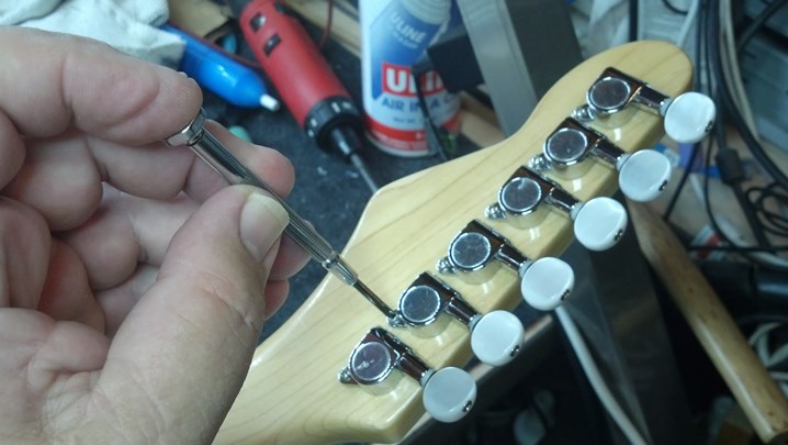
No problems removing the tuners… these screws were busted off as well.

To remove the broken screws, we apply heat to the body of the screw. This dries out the surrounding wood so that it shrinks slightly.

I used the same technique with the wire cutters to grasp the body of the broken screw to twist it out easily.

Rinse and repeat for the remaining broken screws.

Now that everything is apart, I need to fix this neck pocket. First, we get the bottom flat.

Then we get the sides flat. This body was painted after it left the factory, so we have plenty of over-spray in the neck pocket that we need to clear out with this scraper.

I believe that we are down to real wood again.

Acoustic coupling occurs best when the neck and body fit tightly, ‘bone on bone,’ if possible. I really like this wood hardener, which is essentially solid Lexan dissolved in a light solvent.

This raw wood will take a few coats to seal and harden.

As the old cowboy on the cattle drive once said, “Be sure to look back to see if the herd is still behind you.” Periodic fit checks are always a good idea.

This neck is beautiful because of the thick layer(s) of polyurethane finish. However, the polyurethane layer may get in the way of acoustically coupling the neck to the body. Here, I’m hatching the area where I will scrape away finish.

Again, the luthiers’ scraper is the perfect tool for removing finish evenly and smoothly, leaving the surface exactly flat.

That is much better! Not shown: the finish on the end and sides of the neck where it meets the body is also removed.

A pin vise holds the proper-sized twist drill to resize these holes for the Correct pickup screws.

A little canned air clears out the cuttings from the holes.

Over-sized screws held the pick guard in place. The Correct screws are smaller. Here, a small dowel is glued into each hole, which will be re-drilled with the proper-sized hole. This is hide glue shown here; just fine for this duty.

Once the hide glue is cured, each dowel is trimmed flush.

I jumped ahead to show how the Correct screws are nearly flush with the top of the pick guard. Almost factory.

This single-coil pickup reads as an open circuit. That tiny wire is broken.

The tiny wire is broken because these black and white leads can twist around. Hot-glue now holds them stationary.

The pickup is working now. Here is some new, softer foam in place to hold the pickup in position. Leo Fender would have used short pieces of vinyl tubing on the screws to act as a spring, but these covers go all the way to the bottom of the cavity route, so the foam is the best option for this setup. Oh, and you can’t see it, but the copper pulled out when the original foam was replaced, so this guitar has copper in the pickup route and under the pick guard.

Here is the actual pickup.

And here is the separate cover.

The Correct screws are not nearly as hard to drive as the other screws.

More Guitar Fetish goodness! The metal parts of the guitar should be tied to a single point, not at various places along the signal path. This soldered wire ties the metal body of the pickup to one side of the audio path, and has got to go.

That connection is now cut open.

A separate layer of foil is wired to the single point ground. The connection to the bridge and strings is accomplished with another sheet of foil and this outside-star lock washer. Again, the mechanical ground is not part of the signal path.

Everything goes together as it should. See how the star washer makes the connection between the bridge and foil?

The Correct controls are marked T for tone and V for volume. The switch is ready to wire.

The new wiring is accomplished with solid wire in Teflon tubing. The pickup wiring is the vintage ‘push-back’ wire, which is actually really easy to use and can be very clean-looking as the insulation is cut without resorting to wire strippers.

When the control plate is in the correct position, new holes are bored for the screws.

The neck plate needs some attention. This metal polishing paste is also what I use to polish fret wire.

These holes are reamed to the proper size for the Correct screws.

The tuners are going on! A bit of red felt is glued to the face of the socket so that the finish is not marred.
These new screws going into the correctly-sized holes are very well-behaved now.

The truss rod cover screws will now live in properly-sized holes as well. The pin vise is getting a workout today!

The customer uses these strings. We need the guitar strung so that we can get the neck straight.

Note that the outside E strings are equidistant from the edge of the fret board. The screws attaching the neck to the body are tightened at this point.

Now that the neck is properly positioned, we can finish the setup. The truss rod is adjusted to make the neck perfectly straight. Do you see the slip of paper next to fret 9? It is used as a feeler to see that the ruler is in contact with the fret board all along the neck. A piece of paper is about 0.0015 inch thick or so. It is used to check for fit between every fret on the fret board. Yes, that makes a difference!

This neck is brand new, and so the frets had never been leveled. Just a tiny bit of sanding was all it took.

Here I am taking a measurement of fret wire height. I need this shortly to file the nut slots.

Frets are polished.

Fret board is cleaned and conditioned with oil.

Here we are cutting the nut slots to depth (about 0.006 inch plus the fret wire height measurement made earlier.)

Once the nut slots are at the right depth, the rest of the nut is sanded away to make the slots shallow. We need to sand a little bit more away near the high E and B strings, and maybe next to the D string. We’re getting there!

The instrument is back together and sounding good!

This is a closeup of the saddle barrels. These are factory intonated and are VERY close to correct. How do they do that?

Our patient is making her debut at the studio.

First Note.

I think he likes it!
Thanks for reading all the way to the end!
CONTACT – David Latchaw EE
281-636-8626

 This instrument plays beautifully and has no real discernable setup issues. However, the wiring seems to be amiss!
 More than a few of you will have heart palpitations seeing this head stock.
 Two output jacks allow a mono mix of both pickups as is usually found with most multi-pickup instruments, plus a special “Ric-O-Sound” jack that presents the signals from two pickups as two separated signals, accessible with a stereo cable (TRS.) This gives the player the ability to run two preamps, two effect loops, two separate amps, etc.
 Immediately after looking under the pick guard, we find a loose wire. Poor soldering here.
 This isn’t even tinned.
 Here is another broken wire, another ground wire.
 We have a stack of three inside-tooth lock-washers under each output connector. Not much spring action available from the teeth of these locking washers, so they don’t really lock.
 A magnet is the quickest way to clear all this extra hardware out of the control route.
 This is the stereo jack handling the “Ric-O-Sound” duties.
 The mono jack handles the single-ended output from this instrument.
 Soldering workmanship on the switch needs some attention as well.
 Disconnecting each pickup allows us to do some cleanup in the wiring cavity. The neck pickup is ohmed-out. The neck pickup is sometimes called the ‘treble’ pickup.
 And we do the same with the bridge pickup. This pickup is also called the ‘bass’ pickup, which seems redundant.
 Perhaps this soldering was done with plumber’s solder. It is awfully dull.
 Another look at the switch. Not much to brag about here.
 The ground connection to the control is redone. Smooth and shiny is the name of the game when soldering.
 I labelled the controls BV (Bass Volume,) TV (Treble Volume,) BT (Bass Tone,) and TT (Treble Tone.)
 Now that the controls are identified, we can install the knobs in the Correct location. Yes, they were in the wrong place.
 Earlier I pointed out the stack of three inside-tooth lock washers. Here’s why I mentioned it:
 When stacked, the teeth have nothing to push against. The teeth are literally hanging out in space.
 A flat washer in the middle will provide some ‘resistance’ for all the teeth to press against, thus restoring the action of the lock washers to that of being, er, well, lock washers.
 The jacks are Imperial measurement and this washer must have been metric. A little gun-smithing is in order.
 The output jacks are wired and tightened into their correct locations.
 Testing shows no output. It has something to do with this volume pot. What the hey??
 This is the hey. This bit of conductive solder debris was underneath the volume pot, shorting the ‘stapled’ contacts seen in the previous picture to each other, and thus, shorting the output to ground.
 Together again, and it’s playing in stereo!


