Bass players use SERIOUS hardware, and this Ampeg B2-RE is a serious, heavy, high-end bass amp. So why in the world does Ampeg use those tiny little plastic slide pots for the equalizer controls? The Unbrokenstring Crew digs in.
![]() Ampeg is a name that needs no introduction nor elaboration.
Ampeg is a name that needs no introduction nor elaboration.
 Three of the plastic handles are broken off.
 A tour of the rear panel shows the cooling fan, the quarter-inch speaker jacks and Neutrik jacks for output power.
 The preamp and power amp can be separated using these jacks, An effects loop is nice, and a balanced output for the poor sot in the control room is a nice touch. The balanced output has a switchable attenuator.
 A look inside shows a big green circuit board that handles the power amp duties. This view is dominated by the toroidal power transformer on the right. The ribbon cable on the left carries power to and signals from the preamp board.
 And here is the preamp board. Interesting, the slice potentiometers for the EQ are located on their own circuit board on the left side of this picture.
 The preamp board needs to come out to get to the slide pots. This end of the cable comes loose easily.
 Screws hold the preamp board in place in the chassis.
 All the knobs come off, as well as the nuts beneath them.
 The input jack has its own nut and washer.
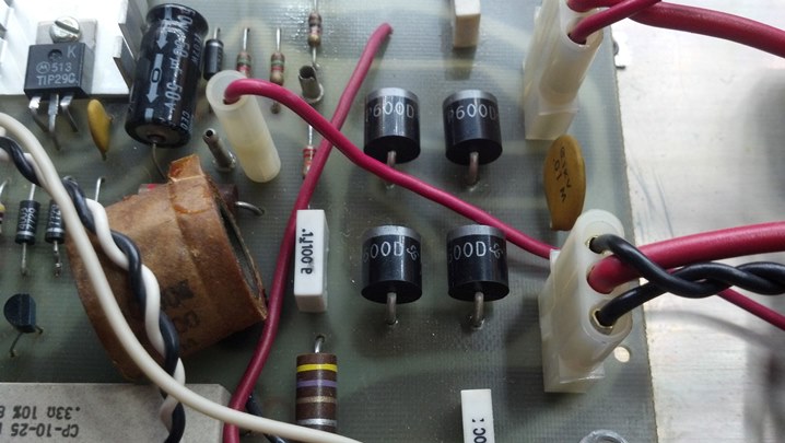
 While we’re here, an inspection of the unit reveals a solder joint on the path to failing. This is an easy fix.
 The slide potentiometers used by Ampeg are special for a couple of reasons. One reason is, they have this nice vinyl flap over the slot that helps keep dust out of the internals of the potentiometer.
 The potentiometer board is held down with these screws and brackets. This needs to come apart next.
 The other thing that makes these slide potentiometers special is that they use three legs to attach to the circuit board.
 Here is the exact part number that needs to be specified when purchasing replacements.
 A similar part is available from other sources, but if you look closely, the ‘pin-out’ does not match. The correct part is in the foreground, and the ‘new’ incompatible part is seen in the background, with the ‘1736’ marking, which is probably a date code of year = 2017 week = 36.
 I was curious if the slider and handle could be removed from the new parts and substituted into the old pots.
 The interior view of the slide pot. The black plastic thingie with the fingers, on the left, is the wiper, and the black strip on the right is the resistive element. The fingers slide along the resistive element to achieve the variable resistor function.
 Oh, drat. The sliders are a different thickness. We won’t be able to use the new parts to repair the old controls.
 So, a week later, a batch of the new controls come in. We are going to change them all out.
 What do you think, folks? Should I clean up the front panel and remove all these presets?
 The new parts are installed.
 The workmanship appears to be pretty good, if I do say so myself!
 Back on the air, this Ampeg is ready to really rumble through its four hour burn-in!
Thanks for reading all the way to the end!
CONTACT – David Latchaw EE
281-636-8626