The customer was headed to the recording studio with his favorite amp. However, our patient has two issues. When the unit operates, the fan is noisy and the output signal comes and goes when you tap around the headphone jack. When you don’t hear the fan anymore, the whole thing has quit. Can the Unbrokenstring Crew make this work AND make the fan quiet at the same time?
 This hybrid combo amp has a lot going for it. Besides being Marshall loud, the unit is light-weight and has some moderately cool features such as a lead and rhythm channel, solid state reverb, a 12AX7 preamp tube for that tube sound, a headphone output, and a CD input so that the aspiring bedroom rock star can play along with their favorite real rock star.
 An unexpected bit of excitement is, this is actually a Bletchley-built unit, factory-built for export to the United States.
 Removing the chassis from the cabinet is straightforward. Here is a view from behind the front panel. The power switch is to the left. The headphone jack and the CD input jack are in the center.
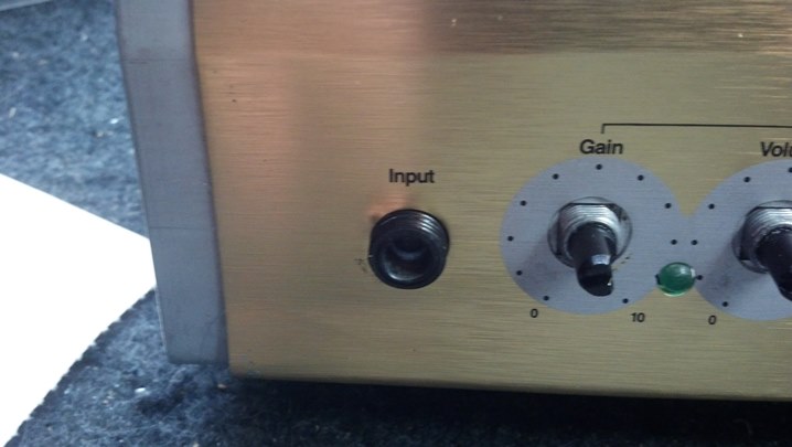
 The front panel controls are those green vertically-mount potentiometers. The input jack is on the right.
 Looking inside the rear panel, we see the IEC power jack. The power transformer and heat sink dominate the center of the chassis.
 The rear panel jacks on the rear panel have their own circuit board.
 We need to remove the main circuit board, as The Unbrokenstring Crew has quickly identified many intermittent solder joints that have caused this unit to quit. We are going to be giving the soldering iron a workout today.
 These pictures that follow document where the cables plug in. All of the connectors are polarized.
 The blue wires go to the final amplifier, which is a high power integrated circuit. Power for the amp is carried by the white wires.
 These cables carry the output signal to the rear jacks.
 More cables. The white wires are the AC mains cables.
 These cables go to and from the power transformer.
 The knobs and now pulled and the retaining nuts are removed from everything.
 The main circuit board is free!
 Now that all those knobs and jacks are out of the way, we can give the front panel a good cleaning.
 The Gibson Guitar Pump Polish does a good job of removing grime and fingerprints. And it smells nice!
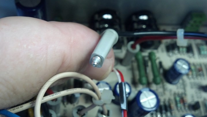
 The headphone jack has a wide circuit board footprint. Here is the replacement jack compared against the output jacks.
 The original shield from the bad headphone jack is moved onto the new part. We’re changing the headphone jack because the preamp output signal goes here and either passes thru to the output amplifier, or goes to headphones. When NOT using headphones, the signal to the output amplifier was intermittent, because of the dirty switched contacts on the original jack. These cost less than a dollar so replacement is faster and better than cleaning the original.
 The headphone jack is 100% now! Because it’s brand new.
 Some of the controls needed to be changed out. The new parts arrived today!
 Have you ever seen a four-terminal potentiometer?
 These are all changed out.
 Next, we need to look at the noisy fan. This is the power amp / heatsink / fan assembly.
 This is an inexpensive 12vdc fan, similar to the ones used in personal computers.
 Perhaps we can oil this guy and shut him up.
 Well, that didn’t work. It’s worn out. Off it comes.
 We can salvage the electrical connector and install it on a new fan.
 The new ‘silent fans’ came as a pair, so this heat sink is going to get two fans.
 This fan is oriented to move some air across a power resistor on the main board. Because I’m an Engineer, that’s why.
 The other fan is oriented the same way as the original fan. IMHO this makes a little more sense than the original setup.
 This is the top view of the final setup.
 When removing cables, a lot more than the cable came loose from the circuit board assembly. See the hole?
 This pin used to be soldered to the board through that hole.
 These pins are tin plate over steel. They have a larger thermal mass than the other components on the circuit board, and therefore MAY have not been at a high-enough temperature long enough to make a good solder joint.
 These pins will be re-tinned with tin/lead solder. The entire circuit board will be reworked to make it NON-lead-free.
 This stuff is rosin-activated solder flux. This enables good ‘wetting’ of the tin/lead solder joint.
 This is a beautiful NON-lead-free solder plate over steel. The whole amp gets this treatment.
 Lots of those pins came loose when the cables were removed.
 Those bad solder joints go a long way in explaining why this amp became intermittent.
 This amp was manufactured while the world was converting to lead-free solder. So, the process guys were still learning what worked and what didn’t work. These didn’t work.
 All of the solder joints in this amplifier were reworked by removing the tin solder and reflowing with tin/lead solder. The Unbrokenstring offers this service for those who wish to have the MOST reliable gigging and recording equipment.
 Lead-free solder is NOT reliable. Exemptions from the lead-free directive (RoHS) have been issued to automotive, avionic, energy/down-hole, and medical electronics precisely because it has proven to be unreliable.
 Here is our new headphone jack again.
 We are ready to assemble the unit. Now where did I put all those knobs?
 Four hours of continuous testing proves that this combo amp is in top shape!
Thanks for reading all the way to the end!
CONTACT – David Latchaw EE
281-636-8626

 This unit has LEDs for the power indicator and a clipping indicator, or something called “Compression.”
 From the school of ‘crank it up and rip the knobs off’ we have a knob that has been ripped off.
 Most of these Peavey heads usually consist of a preamp, mixer, and/or EQ assembly behind the front panel, and a rear panel that holds an amplifier and power supply. The transformer is bolted to the case in the middle.
 We need to get to the circuit board, so all the knobs and nuts come off.
 This unit was built in the era of the Plastic Potentiometer Shafts. Grrr…
 A few screws keep the panel and circuit board flat.
 More screws go into the magnetic parts holder. We are almost there.
 Here, at last, is the circuit board.
 Potentiometers that stand off the circuit board like this are sometimes called ‘spider’ pots.
 These other controls are fine. The values 10K and 50K refer the resistance, and the letter ‘B’ implies that the taper is linear. An ‘A’ letter implies an audio taper control.
 The Alps company made these in Brasil.
 Here is the new replacement part, with a metal shaft! If this were my unit, I’d replace them all with metal shafts.
 The plastic shaft broke off inside this knob. A few minutes with an Exacto knife is all it took to reclaim the knob and cut my thumb..
 The new control is soldered into the circuit board. The factory workmanship on this assembly is pretty good.
 Back together it goes.
 With the knobs in place, you can’t tell that anyone has been here.
 One last look as we reassemble the unit…


