This wonderful old Marshall JCM900 lives in a recording studio. It was due for a set of tubes and a million-mile checkup. Could the Unbrokenstring Crew refresh this head and resolve the tiny issues that had arisen over the years?

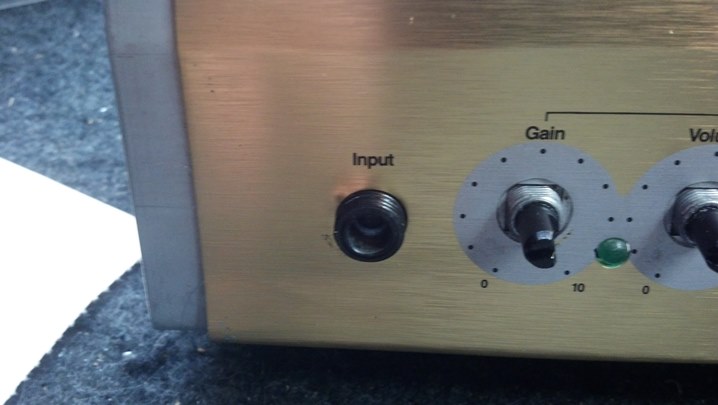
In simple terms, this head has two channels that share a common tone stack, effects loop, and reverb tank. The amount of reverb, as well as the gain and volume, are independently adjustable.

Name, rank, and serial number, please.

The effects loop is accessible from the back. This unit is recording-friendly, with outputs for ‘wet’ and ‘dry’ signals.

The Business End. This amp can be switched to 50 or 100 watt output power.

Two fuses are used in the high voltage plate supply for this amp, which is a nice touch and will add something to the story later. IEC mains power socket and a line fuse rounds out the rear panel.

These power tubes have pushed billions and billions of electrons around, and some of those electrons have interacted with the inert gas inside the glass envelope. Do you see the frowning face in the upper insulator? The brown scorch mark is his beard.

These great tubes have delivered a long service life and are now just about worn out.

Interestingly, Marshall delivered these heads with 5881 tubes, a military 6L6. Later 6L6GCs dissipate more power and take higher voltages. You can read Internet posts regarding the battles between Marshall in England and American importers; the latter changed the tubes on new amps to 6L6GCs because they believed the 5881s would not last through the warranty period.

And here we have the reverb tank.

A walk through the bottom of the unit shows us the output transformer. The red and black leads to to the reverb tank.

On the left is the preamp circuit board containing the input jack, tone controls, and signal switching. The tube sockets are discretely wired, and on the right is another circuit board handling the effects loop jacks.

More views of the preamp board on the left and the output jacks on the right. Tube sockets are in the middle.

At the lower right side of the output circuit board is the power supply power resistors, rectifiers, and fuses

The large blue items are the filter capacitors. These are in excellent condition and will not be replaced today.

The power transformer and power switches are mounted directly to the chassis.

This blue control sets the idling current (bias) for all four tubes. The current splits thru R28 and R29 to manage a pair of tubes each, part of the 50W/100W power control circuit.

The Unbrokenstring Crew are big fans of DeoxIt products. Here, we have sprayed a little D100 into the cap, and then soaked a pipe cleaner in the solution.

The pipe cleaner works well to clean and recondition each individual octal tube socket contact.

We will also wipe off the pins on the bottom of each tube.

So with the tubes installed and operating into an 8 ohm resistive load, we set the idle current for one pair of tubes. But the two sides don’t match.

Here, I’m using my good Fluke bench meter to confirm that one pair of tubes is idling at 50 milliamps, while the other pair is idling at about 41 milliamps or so. Both meters are in good agreement with the values measured, but I’ll stay with my good Fluke to investigate the situation.

Plate current causes heat to be dissipated in each tube. The V1 and V4 tubes are about 114 degrees C. while idling at about 41 milliamps.

The V2 and V3 pair are a little warmer. These tubes are idling at 50 milliamps. The temperature difference confirms the validity of the different idling currents… but why are they different? They share one transformer winding. We paid big money for matched tubes (which, when swapped around, make no difference…) More work!

Remember seeing separate fuses for plate current on the back of the amplifier? Checking voltage drops in the entire plate circuit, we see that this fuse drops about 0.2 volts across it more than the other fuse. Does that tiny voltage drop make any difference?

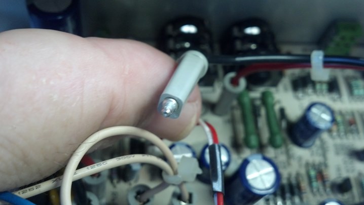
The fuse for the V1/V4 pair of tubes measures over half an ohm (meter zeroed for test lead resistance.)

This is the other fuse, for the V2/V3 pair plate circuit.

This fuse measures a tiny bit smaller resistance from end to end. Does this actually account for the higher current?

Sure enough, those voltage drops and differences in resistance accounts for about 10mA difference in plate current. New Fuses, Please!

While we’re at it, we will clean the fuse caps with DeoxIt, just as we did with the tube pins.

And the fuse holders will be similarly cleaned. (Hint – these pipe cleaners are perfect for cleaning other hardware besides your tobacco pipe.)

This line filter capacitor is scorched by a power resistor that was pushed up against it, perhaps a result of rough handling during shipping.

Components that are used on AC power require all sorts of safety certifications, which this part has.

I could probably leave this part in the amplifier, but film capacitors are cheap and if this were my amplifier, I would want it taken care of in a proper manner.

So here is the new line capacitor. The power resistor will be moved away from this guy when it is installed.

The filter capacitors in the bias circuit were also replaced, while troubleshooting the plate current imbalance.

Of course, replacing those parts requires access to the bottom of the circuit board.

While we have the circuit board up and out of the way, we can catch a glimpse of the discrete-wired tube sockets. This is a much better way to wire vacuum tube sockets, rather than solder them to a printed circuit board IMHO, because the tube sockets expand and contract much more than the circuit board material, whereas the discrete wire can just flex with the expansion and contraction.

This little bit of trimmed wire was stuck on the bottom of the circuit board. This will be no issue unless it comes loose, which it might do just as you are ready to go on stage and start the set.

Now this amp is running like a clock. The waveform represents the voltage across eight ohms driven with 110 watts, with a 440Hz sine wave injected into the input jack.

The chassis goes back into the case. I removed the power tubes for this step because I didn’t want to risk breaking anything in case I got stupid. The red and black cables to to the reverb tank.

Everything is checking out!

The sheet metal rear panel is much easier to align when the unit is face-down on the bench.

Zenith televisions were advertised with the slogan “The quality goes in before the name goes on!” After a four hour burn-in, the sticker is affixed on the output transformer side of the rear panel.
Thanks for reading all the way to the end!
CONTACT – David Latchaw EE
281-636-8626