This preamplifier and microphone processor is in the audio chain of every hit produced by Majic$tyle Studios over in Houston’s 3rd Ward. But it quit one day. So the music quit. Could the Unbrokenstring Crew help the Majic$tyle Crew bring back the music?
 Like many recording facilities around Houston, the modest studio in the back room has a lot of history. A lot of talent in the Houston Urban Contemporary and Hip Hop scene have stood in front of this box, layin’ it down.
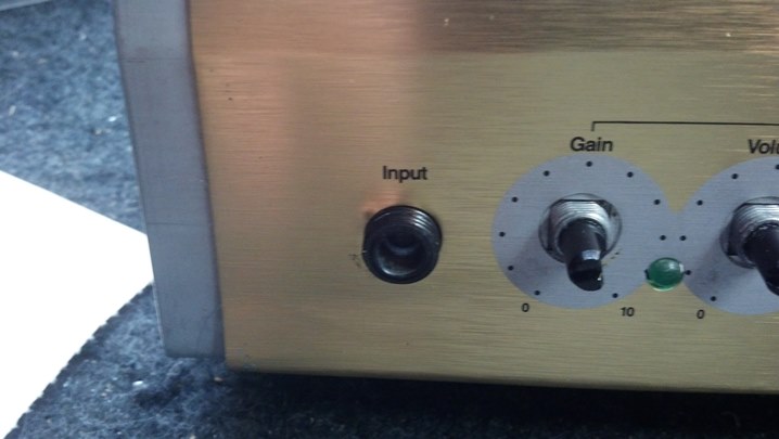
 This unit needs an overhaul. A quick tour of the front panel reveals input level controls for two channels.
 Phase and tone controls are here. The tone control can be completely bypassed, which can be useful.
 These inexpensive meters actually do a pretty good job of displaying dry level and processed (wet) levels for each channel.
 The ‘warmth’ is another term for the wet signal, routed through a starved-cathode tube circuit.
 Power input and device info is found on the back.
 All of the inputs and outputs are on the back.
 The cabinet screws are a different length. This is noted.
 The DC power management and toroidal line transformer are located in the center.
 All of the rear panel wiring is done with a circuit board, with the wiring harnesses glued to the chassis.
 We are missing some DC voltages, so our investigation will focus on this circuit board. What a heat sink!
![]() Toroidal transformers are the way to go in high quality audio equipment.
Toroidal transformers are the way to go in high quality audio equipment.
 Behind the front panel, we see a pair of 12AX7 dual triodes living on this circuit board. The incandescent light bulbs are burned out, but are for aesthetic purposes only. We will have some fun with these!
 The rest of the front panel circuit board is almost entirely encased in sheet metal, as shielding.
 I documented these cables, in case I needed to disturb them.
 Can you see the bulged electrolytic capacitor?
 Hot glue is used to keep all the connectors connected and all the big parts from moving around.
 With the wiring harnesses removed, this circuit board is held in place by screws that fasten the power semiconductors to the heat sink. When those screws are removed, the circuit board assembly can be repaired.
 Remember the bulged capacitor? It leaked out the bottom.
 This power supply will get a full cap job.
 The electrolyte from the leaking capacitor has chewed away some metal from the circuit board and a couple of the solder joints. This will need to be taken into consideration when the new parts are installed.
 The blue jumper wire restores continuity on the corroded trace seen in the previous picture.
 New caps are installed!
 Here is another view of the new skyline of our power supply board.
 Heat sink grease is used to insure thermal transfer from the power semiconductors to the aluminum heat sink. This tube of compound will probably live longer than I will.
 The tabs of the power semiconductors SHALL BE isolated from the heat sink. Here, an ohm meter checks for isolation.
 Those incandescent light bulbs are not part of the signal chain, but just serve as a back light behind the vacuum tubes.
 These are 24v bulbs. I could just replace them, but why would I pass up a little fun with just a stock replacement part?
 The tip of the base of the bulb is actually a specially shaped bead of tin/lead solder, which holds one of the terminals from the filament of the light bulb. So, I desoldered it.
 One of the leads from the filament goes to the side of the metal base of the bulb. So I unsoldered as well.
 This is a better view of the base, showing the central terminal.
 The glass bulb comes out. Besides the broken glass, you can see bits of glue on the rag.
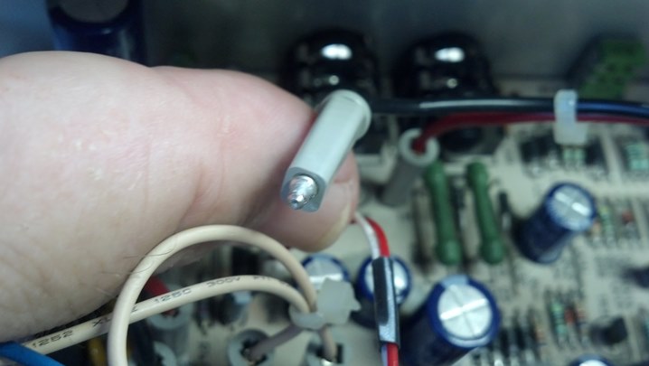
 The plan is to add LED lights in place of the bulb. This is the series limiting resistor for 24 volt service.
 It hides inside the base, as shown.
 These red LEDs are built on top of the resistor and are supported by the bulb base. This is gonna be cool.
 The meters are also internally illuminated. These meters will get yellow LEDs.
 The front panel will get a million-mile cleanup and polish. Off comes the knobs.
 These bushings keep all the knobs turning smoothly.
 Now that the front panel is free, it can be cleaned and polished with Gibson Guitar Polish.
 Removing the knobs is the only way to get the grime out from down around the knob shafts.
 The clear windows are polished on both sides.
 Behind the aluminum panel, we have rotary encoders for the wet level control duties.
 All the low level audio is contained on this double-sided circuit board. Any copper that isn’t signal is audio ground.
 The switches are cleaned and lubricated.
 With the front panel removed, this chassis is just floating.
 Let’s take a quick peek underneath the audio shield.
 Audio gain duties are handled by TL074 opamps.
 Here are the microphone preamp chips. These are surface-mount JRC4580s.
 Here is the other mic preamp 4580. OK, we’ve done our gut shots for the day.
 Now let’s get these meters done. Hot glue is everywhere.
 Once these meters are removed from the front panel, they can be easily serviced.
 The lens and front bezel come right off.
 So far, we haven’t destroyed anything.
 The meter scale just lifts out of the body of the meter.
 Here is where we are so far, keepin’ it real.
 If we peer inside the body of the meter, we can see a ‘grain of wheat’ lamp. These are all burned out.
 I will attempt to reuse the leads to each of the bulbs. The burned out bulb is removed.
 To get a little bit more room to move around, I’ve removed the meter movement. Be very careful!
 The meter bulbs are 12 volt units, and two of them are in series because only 24 volts is available. This is the LED current-limiting resistor for one of the meter illuminating LEDs.
 I purchased a bunch of these 1% resistors years ago from Texas Instruments (TI) and so these are probably collectors items. Why not use them on this project?
 Here is the yellow LED and resistor installed inside the meter body.
 Now the meter face is reinstalled.
 The clear lens is popped out of the bezel for cleaning and polishing.
 Everything is reassembled and the meter movement is zeroed. Ahhh, that’s done!
 This shield was loose under the circuit board assembly that held the tube sockets. What’s up with that?
 Turns out, these standoffs were unscrewing from the bottom. More LokTite, please.
 This is going to take three hands.
 Unfortunately, I only have two hands. But The Unbrokenstring Crew can make it happen!
 Let’s reinstall the front panel and do a final assembly.
 The meters are gently torqued onto the panel.
 The knobs and bushings are restored. This is starting to look nice!
 The red and yellow LEDs are doing their job. Unfortunately, the .jpg engine in my phone camera is making the red LEDs behind the vacuum tubes look a little gaudy. Oh, well. More importantly, this mic preamp works well and is DEAD SILENT with no input signals. I think the rebuild went pretty well!
Thanks for reading all the way to the end!
CONTACT – David Latchaw EE
281-636-8626