Fender Princeton Reverb Amp is Snatched from the Jaws of Hurricane Harvey

Partially submerged in the flood waters of Hurricane Harvey, this combo amp was rescued when the waters receded.  Could the Unbrokenstring Crew turn this insurance claim into a working unit again?

 At first glance, this unit is in pretty good shape.  Fortunately, the flood waters around this unit were not salty, but fresh rain water.  The grille cloth was not badly stained, and much of the exterior grime was superficial.


Not much damage had occurred to the cabinet; some warpage was beginning to appear in the bottom baffle.  The interior was still wet.  This implied that, if the drying-out process could be controlled, no further damage to the cabinet would be sustained.


Can you see some rust on the screws?


This side has some mold.


The bottom Tolex has some mildew beginning to form.  Look at the rust beginning to form on hardware in the foreground.


The handle was beginning to rust.  This could be managed.


The handle and the Tolex is cleaned and reconditioned with this, which also gives us a clean lemon scent!


This is the top of the reverb tank.  Yes, beads of water, still on the exterior of the tank.


The previous owner had padded the top of the tank with gray foam, and the bottom with cardboard.  The cardboard was soaking wet.


Reverb tanks are inexpensive, so we will just order a new one.


The paper cone of the loudspeaker was intact.  This loudspeaker will be replaced by the new owner.


Moisture inside the amp chassis has swelled the turret board.


Water has reacted with the solder flux, creating a brown crust around all the solder joints.  The components still look pretty good, although they cannot be trusted now.


Corrosion on the tube socket contacts testifies to the presence of liquid water here.  Note also that the zinc plating on the once-shiny chassis is turning cloudy.  This tells us that the zinc is doing its job as a corrosion-inhibiting plating, sacrificing itself to protect the steel underneath.


The cabinet hardware is washed in Rust Biox to clear away the rust.  This chemical is available in Europe, but of course, The Unbrokenstring Crew is just cool enough to have this material here in the U.S.


The nickel plating has very little iron to rust;  This deposit is probably mud.


All the hardware is cleaned up.  The Tolex is cleaned and conditioned with the furniture polish.  The cabinet looks good as new!


A new tube chart is pasted inside the cabinet where the original one was located.


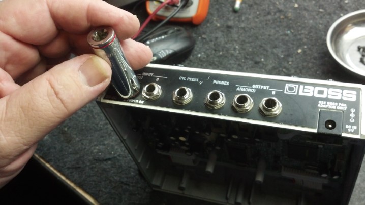
For the electronics, a hand-wired chassis from the estate of Darrell Shifflett of Texas Amplification is pressed into service.  The Unbrokenstring was truly fortunate to buy the remaining inventory of Texas Amplification.  This chassis was part of the inventory.  Look at those shiny new jacks!


The knobs are, of course correct.  This is a clone of a Fender Blackface Princeton Reverb, not built in California but rather in Houston, Texas.


Darrell was a master of the details.  Even the front panel is Correct for this unit.


As a testament to Darrell, let’s just take a look at his workmanship.


The wiring and component placement is meticulous.


If original components were available, such as the carbon composition resistors, he used them.  Modern flame-proof components are used where an improvement in reliability and safety without sacrificing sonic performance justified the upgrade.

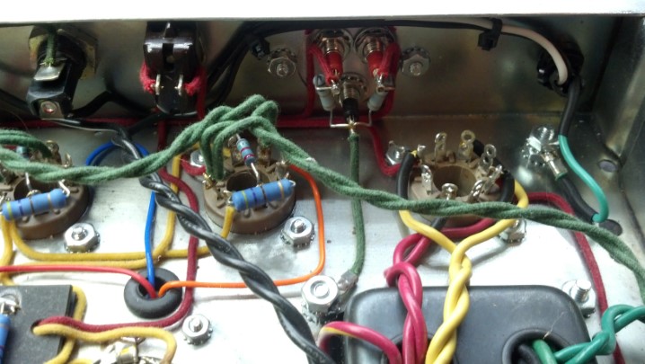
Even the wire is period-correct, fabric-covered was used for the point-to-point wiring, just like the originals.


A bias check for EACH output tube is added to the rear panel.  Millivolts measured from red to black correspond to milliamps of plate current.


The jacks and controls are name-brand and not the cheap stuff.


But just look at that fresh brass sheet used for the ground plane under the controls.  The original brass probably didn’t look this good in Fender units when they were new!


The underside of this amp is just a voyage on the Good Ship Eye Candy!


The electronic tremolo circuit is duplicated on this turret board.  Not sure why this turret board is warped, but it is electrically 100%.


Speaking of turret boards, just look at the meticulous care used to mount each component and route the leads.  Even the bias potentiometer is nicely placed.


Comparing this layout against the original Fender drawings is just breath-taking.


I’m really jazzed about how the fabric-covered wire is carefully routed around the tube sockets.


We needed a new rectifier tube for this amp.


Darrell used Mercury Magnetics for all the transformers on this chassis…  the best you can get!


With the power on, all the voltages are correct.


The new reverb tank arrived today.


The bag protecting the reverb tank is dry and ready to be used again.


These straps hold the reverb tank bag in place in the bottom of the amplifier.


The ON/OFF switch works as it should.  Since the AC cord is a modern three-wire unit, the original ‘GROUND’ switch is wired as a STANDBY/ON switch.


This unit is ready to go back to the new owner, who will install the new loudspeaker.  Pretty nice unit for having been under water!

Thanks for reading all the way to the end!

CONTACT – David Latchaw EE
281-636-8626

A Journey To Planet Unobtanium – Yamaha 50-112 Combo Guitar Amp

A secret weapon of many an acoustic and jazz artist, this mid-seventies line of Yamaha solid state amps were well-regarded among those few who knew about them. This like-new specimen had been suffering from a strange ailment, then went mute. Could the Unbrokenstring Crew revive this unit?

On the exterior, this amp was in very good shape considering that it had been built forty years ago!


Starting our tour, the power switch combines the ON/OFF function with the AC polarity reversal switch seen on many tube amps of the same period.


The high and low level input jacks are typical for the era.


The tone stack includes a ‘bright’ function, a precursor of the ‘presence’ control seen on amplifiers today.


The presence of the reverb function demonstrates that this is an early unit.  Many of the later ones did not have a reverb tank at all.  The distortion function is an attempt to add ‘fuzz’ and is nothing like the metal/shred distortion heard today.


A few attempts had been made over the years to clean the controls.  Unfortunately, the lube spread onto the front panel around the controls.  Yuck!


The open cabinet is clean and functional.


We have the usual name-rank-serial number information here.


We have two unmarked jacks.  What in the world?  But we see foot switch jacks which are not out of the ordinary.


Both the AC power into the unit and the DC power to the final amplifier block are externally fused.


And, we have a QC sticker!


Removing one of the rear baffles reveals the solid state amp and gives us access to the chassis.


Obviously the original loudspeaker, the response graph demonstrates the heritage of this unit to the high fidelity world that Yamaha dominated in the 1970s.


This ground lead connected the chassis of the amplifier to the frame of the loudspeaker.


With the chassis out of the cabinet, we see a reverb tank in the foreground, a power transformer to the right, big capacitors in the center, and a mono-block amplifier to the left rear.


This strain relief for the AC power cord is really over-the-top!


The black, finned heat sink is the foundation upon which the power amplifier is built.


This large electrolytic filters the DC power for the amplifier, which is nominally 80vdc.


This electrolytic capacitor is in series between the amplifier output and the loudspeaker.  This amplifier’s circuit topography shifts the DC operating point of the amplifier to one-half of the DC power supply voltage, effectively forming a class AB amplifier using a single power supply.  This capacitor passes the audio current to the loudspeaker while protecting the loudspeaker from any DC current.


Underneath the chassis we find this fused, low-voltage power supply which supplies floating DC voltages for the circuitry.


Remember those two unmarked jacks on the rear panel?  Someone added them so that a quarter inch cable can be connected to another quarter inch cable.  Yes, this is a home-made 1/4″ mono to 1/4″ mono jack adapter/coupler.


Here is the bottom side of the two large electrolytic capacitors we saw up top.


More fuses and bypass capacitors are visible here, in vinyl tubing, to shroud the terminals from touching something they shouldn’t.


The ON/OFF/ON switch is seen to the right and the Power ON indicator lamp, with limiting resistor, are seen here.


Look at the thick steel shield that keeps any signals running around the inside of the amplifier away from the input jacks!


While we’re here, let’s service the unit.  Jacks are cleaned with De-Ox-It.


This circuit board handles all the signals surrounding the front-panel potentiometers.


These controls will be properly cleaned and re-lubricated.  And we can clean that nasty front panel while we’re here!


After removing two large bolts, the power amp assembly lifts off.


The six pin connector handles power in, signal in, and amplified signal out duties.


Inside this assembly, we see all the components for a transistor-based solid state power amplifier.


A pair of these transistors handle the power amp duties.  The screen separates everything from the collector of the transistors, which are at +80vdc potential.


This screw under the little bump in the sheet metal holds a temperature-compensating diode array in close contact with the heat sink.  This diode array provides temperature compensation for the transistorized amplifier.


Note that this module is stamped 50W/8 ohms.  The Japanese think of everything!


With the cover removed, we can see the inner details.


These low-level driver transistors are pure unobtanium, which means that if they are bad, there is no modern direct replacement.


Fortunately, all of those low-level driver transistors appear to be OK.  The curve tracer indicates that this is a PNP device.


This is another bit of pure unobtanium.  Three silicon diodes with special forward voltage characteristics over temperature are housed in this component.


This diode array appears to be functional for now.  These are HIGHLY SOUGHT AFTER by techs who rebuild those 1970’s era Kenwood and Pioneer stereo receivers.


Every component will be checked, including the power transistors.  Replacements are available for these, if we need them.


Almost every component will be removed from the circuit board and verified against the schematic and the markings on the device.


This capacitor was more than 30% low in capacitance, and will be replaced.  (No, the leads are not touching.)


With the power amp assembly back together, we can perform some initial setup of voltages and levels.


One of those two big power transistors with the copper-colored tabs is intermittent.  Can we find a matched complimentary pair to replace them both?


Yes, after some research, an adequate replacement was ordered.  Whew!


Here they are, those black boxy devices in the center of the picture.  I marked the collector pin locations with a C and the base pin locations with a B on the circuit board so I could get the new parts in the right place.


OK, now we’re cooking.  The center yellow trace is a signal called C.VOLT on the schematic, and represents the voltage value of the midpoint of the DC power supply.


Over a few hours, the value of C.VOLT changed, creating bad distortion.  Look closely at the green capacitor at the top of the picture.  Can you see something ‘wet’ on the circuit board under it?


That ‘wet’ looking stuff is similar to contact cement.  The Japanese used this stuff extensively in the 1970s to secure electronic components so that they did not come loose from the circuit boards when shipped to the United States and elsewhere.  Over time, this ‘stuff’ becomes conductive, which will upset circuit operation.  Many a Japanese-built bit of electronics, including televisions and Ham radios, were taken out of operation by this stuff.


The site where the green capacitor goes has been cleaned.  This needs to be repeated for any ‘stuff’ remaining in this unit.


Here is the C.VOLT test point.  The crusty brown stuff is solder flux, which will also be removed.

I uploaded a video of the working amplifier to YouTube, which then blocked the video and hit me with a take-down notice about a minute after I uploaded it.  The audio content of the video was copyrighted, and I was caught.  Don’t you just love YouTube/Google/Facebook?

Thanks for reading all the way to the end!

CONTACT – David Latchaw EE
281-636-8626

Phonic 1500 Rack Mount Stereo Amp Repair and Update

Billy was running this amp as part of his PA for years until one channel quit.  Could the Unbrokenstring Crew bring this inexpensive amplifier chassis back from the e-waste pile?
To some folks, Phonic and Professional do not belong in the same sentence.  But this unit has been working very well behind the scenes, for more years than many of its Brand Name Brethren have been working.


Simple controls on the front.  Cranked to eleven, of course.


It doesn’t get much simpler than this.


Billy asked to have an IEC power cord installed on this when (not if) we fixed it.


The Neutrik power connectors are a nice touch, almost required at higher power levels.


Inputs are either balanced quarter-inch TRS or XLR connectors.  The usual set-and-forget controls are found here.


The power transformer seems adequately-sized for this power level.  AC-to-DC duties are performed to the lower right, and one audio channel is seen between the transformer and the aluminum heat sink.


With the unit turned around, the other audio channel is found here.


The front panel controls are here.  These potentiometers will get a million-mile cleaning and lubrication.


The dark charcoal-colored ribbon cable connects signals to the two audio channels.  The flat ribbon is Just The Thing here, because it does not block the path of cooling air into the unit.


The electrolytic capacitors are bulged, which is not unusual for a unit that has seen this many years and this much use.


These electrolytics will be replaced.


These rectifier blocks are wired in parallel.  Yeah, Baby!


I was kinda wondering where the line fuse was located.  It’s under this bundle of cables.  Yes, that says 30A at 115VAC.


Before the unit comes apart, I need to document where all these cables go.


These cables need to go back where they started.


Behind the colorful bundle in the foreground is the circuit board that connects the rear-panel output connectors.


I need to remove the larger circuit board to get to the solder-side of the PCB.  The dirty little ribbon cable comes off first.


These output cables come off next.


And now, we begin.  There are about thirty screws that hold the circuit boards in place.


These little screws are everywhere.  Like that’s a bad thing…


More screws.


The heat sink is split into two sections, one for each channel.  They need to come loose from the chassis as well.


This aluminum block bridges the tops of the heat sinks to add strength and rigidity to this unit.  Nice!


OK, the main board is out of the chassis.


Interestingly, some other version of this amplifier uses more electrolytic capacitors.  In this version, the pads are jumpered.


Turning the board over, the solder joints to be cleared are ‘marked’ with some rosin solder flux so I can find them if I look away to grab the soldering iron and braid.  Yes, I’ve unsoldered the wrong solder joints in the past.


The old caps at the top of the picture are out and the holes in the PCB are cleared.


Meanwhile, back at the ranch, we will remove the captive line cord and add the IEC connector here.


This cord has 14AWG conductors in it.  A matching large molded IEC power cord will be supplied with this unit when it is returned to the customer.


Here is our new IEC male socket.  Some of these come with flange ears, but spacing on the rear panel is too tight to allow the use of one of those.  This one snaps into place.


This looks a little rough, but this is the approximate outline of the rectangular cutout for the new IEC connector.


While we are hatchet-ing on the rear panel, these magnets will catch any chips or bits of steel removed from the hole.


Here is the outside view of the first trial fit.


And this is what it looks like on the inside.  This IEC socket snaps into the hole, so the hole size needs to be right.


Here is the new IEC socket wired into place.


And this is the closeup of the finished installation.  That silver thing next to the CE mark is a ground point.  I temporarily removed the thumb screw while grinding on the chassis.  It goes back on the unit next.


Now it’s time to reassemble.  Screws, anyone?


Glad I took all those pictures of where these wires went!


The unit is now reassembled.


Here, the terminal block outputs are tested at 250 watts.  So far, so good!


The Neutrik connectors are tested next at 750 watts per channel.  All is well!


Thanks for reading all the way to the end!

CONTACT – David Latchaw EE
281-636-8626

Ampeg BA115 Bass Amp Falling Apart (Literally)

Back in August of 2017, one of these combo bass amps came through the Unbrokenstring Shop with cracked solder joints, which were probably a result of brittle lead-free (RoHS) solder on the circuit board.  The owner of this Ampeg saw that post and called up the Unbrokenstring Crew to ask if this amp could be fixed as well.  Here we go!

Disassembly and reassembly of the combo amp is exactly the same as was performed on the earlier post.  Here, we are starting this blog post with just the chassis on the bench.


Name, Rank, and Serial Number, please!


From above, everything appears to be as it should be.  No wires are hanging loose as was seen in the amp serviced in August, 2017.


But once the circuit board was removed from the chassis, this rotary switch came loose from the circuit board!


As was seen in the other repair, the metallurgy involved with the soldering process was to blame.  In addition, in my opinion, this switch was not the exact part that matches the footprint on the circuit board.  Note that the pins are bent inward to the center of the switch.


These pins are plated in gold.  This is a good thing for the component, but gold, in solution with molten solder (yes, the metals mix) makes the resulting solder joint brittle.  Here, some activated rosin flux is added to the gold plated pins to prepare them for a coat of tin-lead (non-RoHS) solder.


Tinning is complete.  In this picture, we can see the intentional bending of the legs to match the holes on the circuit board.


This is a high quality part, and works well in this application.  However, the manufacturing engineer at SLM was off his/her game that day.


Our new solder joints will probably outlast the amplifier.


No parts were required for this repair, only labor.  This unit plays 100% now!

See the previous Ampeg 115 post for reassembly.

Thanks for reading all the way to the end!

CONTACT – David Latchaw EE
281-636-8626

Boss DD-20 GigaDelay Pedal Needs Direction

Every function on this pedal works properly.  Except, the user cannot select menu functions without a lot of hassle.  And, the delay time can only be increased, not decreased.  Can the Unbrokenstring Crew decode the mystery and make this unit a little less of a pain in the rear to use again?

The unit turns on and works, but the delay time knob only increments.  This makes it almost impossible to select any function or mode unless the user spins the knob all the way around to wrap back to the beginning of the menu.  And there is, like, three hundred menu items.


Everything is accessible from the bottom.  The vertical strips are Velcro hook material, to hold the pedal in place on the pedal board.


The black plastic rectangle on the left is a battery box.  On the right is a stack of circuit boards.


Removing the circuit boards involves removing the nuts on these jacks.


The ribbon cables interconnect the two main circuit boards.


The metal piece around the jacks is really part of the noise shielding of the box.


We can tip out the bottom board now that the jacks and power adapter jack is free from the rear panel.


Interestingly, this little crescent moon-shaped piece is a bushing that makes a small hole out of a large one.  This may have been a design feature for another model of pedal, or, more likely, the result of an engineering change.  Or, my favorite theory, a design screw-up.


Back in the early days of electronics, stiffened cardboard was coated with wax to make insulating sheets called ‘fish paper.’  Nowadays, we have synthetic equivalents.  This insulating sheet separates the two circuit boards.


To gain access to the top circuit board, we need to remove the control nuts on the top side.  This is the knob for the delay select function.  The knob works fine, the function it performs does not.


This plastic bushing covers a larger hole and allows the knob to be recessed below the plane of the top panel.


These other controls are more conventional in their mounting scheme.  Those hex drive screws are for looks, and only hold the bezel down on the top of the pedal enclosure.  We don’t have to mess  with them today.


At long last, we are able to remove the upper circuit board.


We already have a pretty good idea that the rotary encoder for the delay function is not working properly.  To verify that, the unit is partially reassembled for electrical test.  The cardboard is more insulating material to keep everything from shorting out.  Kinda like home-made fish paper.


The unit is running and the oscilloscope can tell us if the two phases of signal are coming from the rotary encoder.  The answer is, one phase is missing.  Thus, the rotary encoder can only appear to electrically ‘spin’ in one direction.


So, it’s time for the old rotary encoder to come off the circuit board.  A soldering iron will melt the solder and this Solda-Pullit will remove the molten solder.


The new rotary encoder is installed, as shown.  This rotary encoder also has a built-in momentary switch that is actuated when the shaft is pushed down towards the circuit board.  Or, in use, when your foot taps the knob while playing.


Pretty nice workmanship, wouldn’t you say?


Re-assembly is the reverse of dis-assembly.  There are a lot of parts here, so this unit will go back together with the help of all the pictures we took earlier.


The insulative sheet goes here.


The bottom assembly goes here, with the requisite white cables.  Don’t forget to re-install the little crescent-moon-shaped piece where the connectors poke through the back panel.  I did, the first time.  Oh, yeah, and the metal shield, too.


Many of the Boss pedals use this barrel connector for power.  The shell of the pedal housing slide into the slots molded in the connector to firmly hold the power connector in place.  Note that not all barrel connectors have these slots.  If you ever replace a Boss pedal power connector, verify that the replacement part has the slots.


This is a little better shot that shows the proper orientation of the shield plate.  The little sharp fingers around the outside edge should point away from the middle of the pedal, so that they can ‘bite’ into the pedal housing.


The red and black cable carries power from the internal battery box that we saw in the picture above.


The unit is cleaned up and all the knobs reinstalled.  Ready for test!


All functions work flawlessly, PLUS the rotary delay time knob both increases and decreases delay time and allows the user to scroll up and down through the menus.  I think we’re done here!

Thanks for reading all the way to the end!

CONTACT – David Latchaw EE
281-636-8626