Peavey Citation MK IV Two Channel Guitar Amp Head Repair

Rod had this Peavey head kicking around and thought it was time to put it to good use. However, it didn’t work at all. Could the Unbrokenstring Crew work its magic and bring this road warrior back to life?
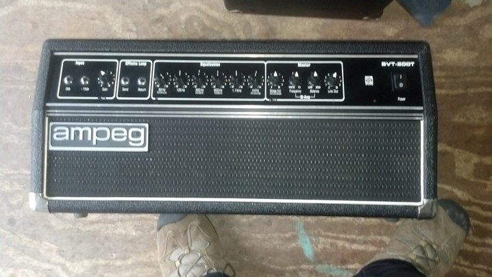
A quick scan of the front panel shows that the input circuit sports the sort of flexibility that the Peavey Marketing Department loves to explain to anyone who would listen…
Each channel has independent gain, and a master volume to Rule Them All.  Effects can be inserted via the front panel.
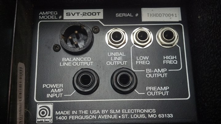
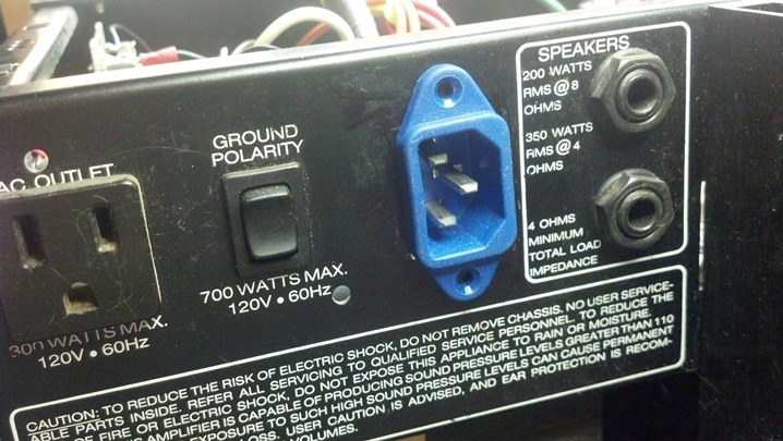
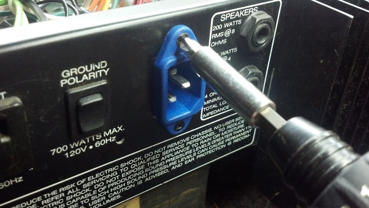
On the rear panel, we have parallel speaker jacks and the usual ground/no-ground power switching.  Peavey often married different front panels, which contained preamp circuitry, to different rear panels, which carried power and audio amplifier components.  The ‘series’ number goes with the power amp, not the front panel.  We Got This.
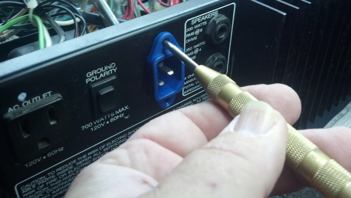
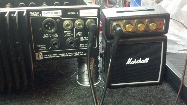
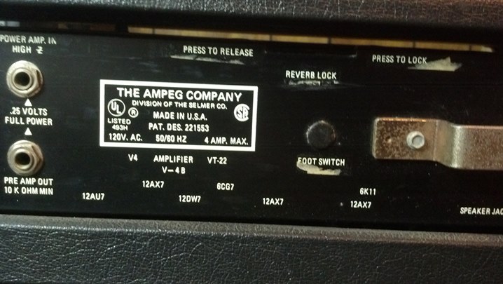
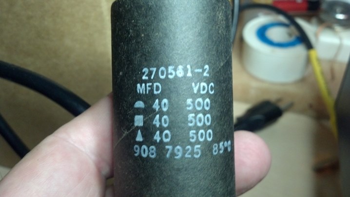
Name, rank, and serial number, please.
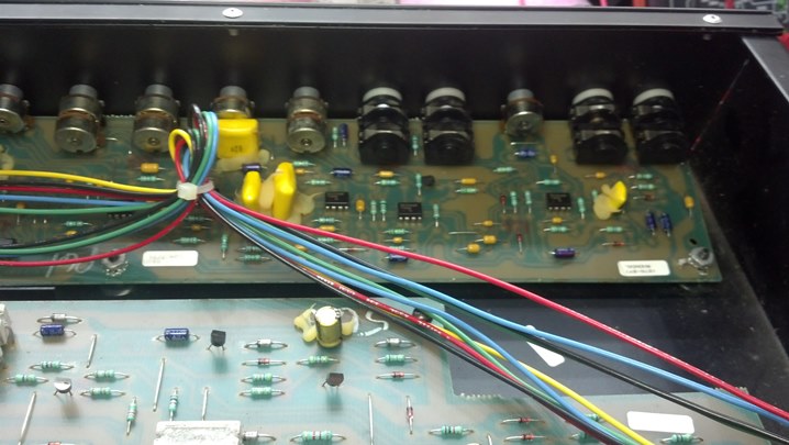
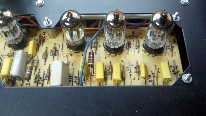
Pulling the front panel, we see that all of the components are mounted on one circuit board.
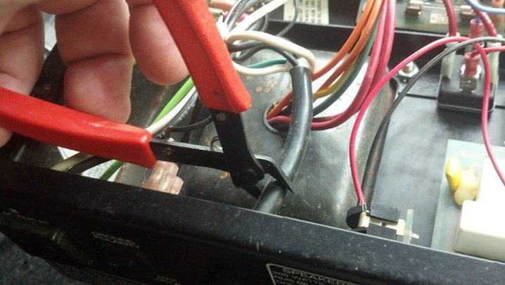
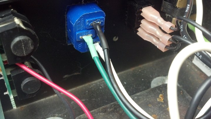
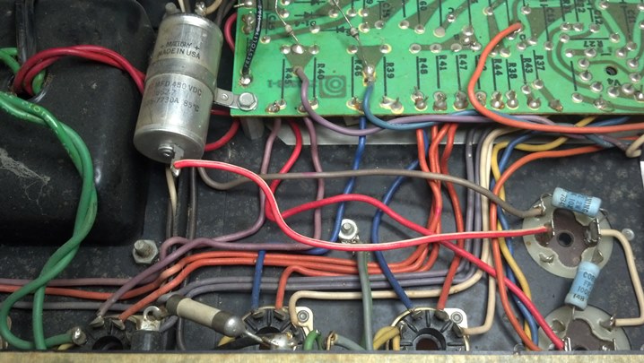
I took a few pictures to be sure that the wiring and cables were returned to the same spot when we are through.
The cable to the right is just wired to the power indicator.  The other two carry signals.
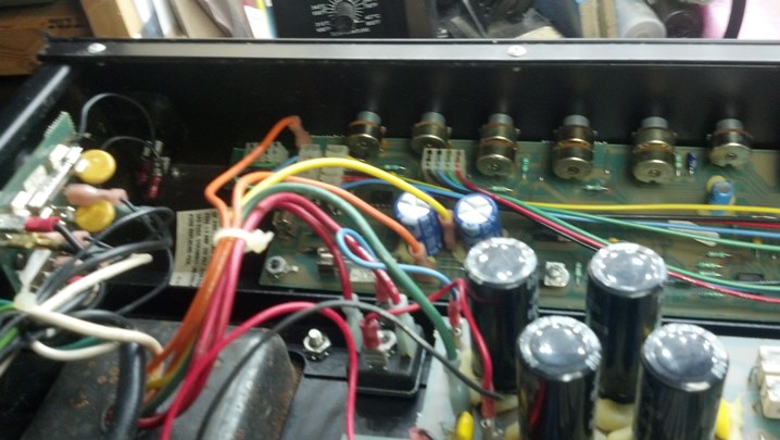
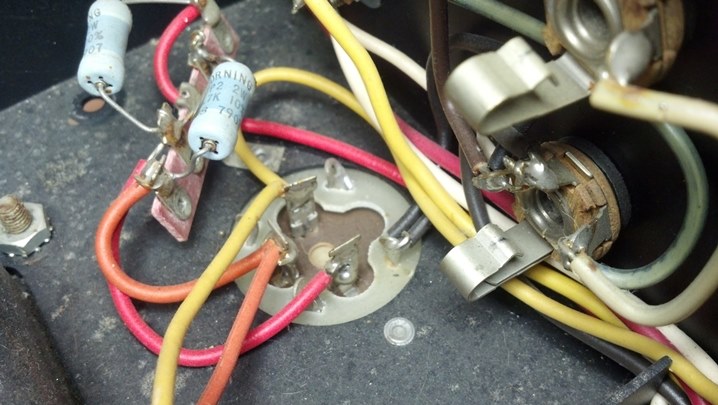
This is a better view (to be sure that they cables are properly oriented on their pins.
The front panel is free of the rest of the unit.
All of the controls and switches will be cleaned so this assembly comes completely apart.
We can now clean and lubricate everything now.


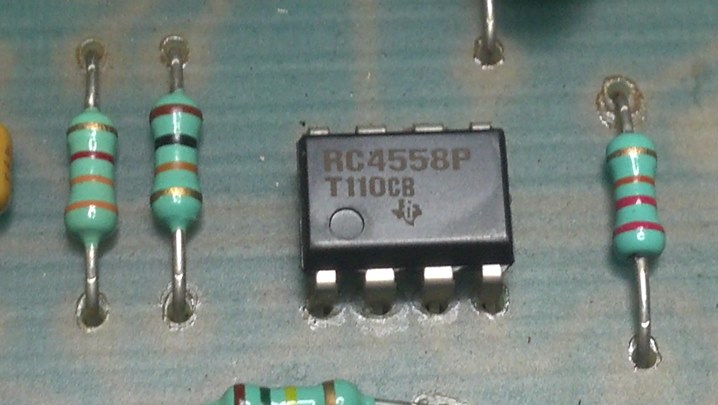
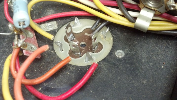
Can you spot the broken solder joints?
Someone has been here before!  This needs to be cleaned up, too.
The Blue Shower is a good cleaner.  The DeoxIt contains a lubricant for the potentiometers.  Good Stuff!
Back Together it all goes!
This screw hole was stripped out.  First, we will soak the stripped hole in the wood with this wood hardener.
Next, a birch dowel is cut to partially fill the hole.  The dowel reduces the apparent diameter, allowing the screw to hold.
With the stripped hole repaired, we are back in business!
This unit plays very well, and all the controls and switches are Like New!


Thanks for reading all the way to the end!

CONTACT – David Latchaw EE
281-636-8626

Sovtek Small Stone Pedal Refurb and Update

The modulation rate control on this wonderful Sovtek Small Stone phaser effect pedal had broken. While the unit is in the shop, could the Unbrokenstring Crew also add a 21st century DC pedal power jack to the unit?

Like a message in a bottle, this pedal has the look and feel of a relic from another planet. Even the switch looks like alien technology.

Removing the top cover reveals a heavy steel plate that holds the major components.  Look at the LED holder!

The control for the phase modulation had disintegrated.  Not much was left holding the shaft in place.

The back side of the modulation control was not out of the ordinary beyond the Cyrillic alphabet. Perhaps it could be rebuilt using parts from another similarly-sized potentiometer.

We have removed the old potentiometer from the circuit.

The tabs on the back cover of the potentiometer can be peeled back in order to disassemble the unit.

Interestingly, the internals of this control are completely different than what we might expect from a domestic control.  This potentiometer is a ‘reverse audio taper’ component.  The Russians achieved this by mounting the resistive element on the opposite side of the main wafer of the control, effectively reversing the direction of the taper.

So, it appears that we need to find a control that is close to the physical size of the old part, so we can reuse the knob.

We are working in millimeters here, in case you are wondering.

An aluminum bushing allows this smaller shaft to fit in the Russian knob.  Perhaps we have another degree of freedom in our search for a proper replacement.

This bushing can be removed…  a good thing that will allow us to do some gun-smithing if we need to do so.

The knob is not quite big enough to allow a quarter-inch shaft to be substituted.

So, we located a reverse audio taper control custom-designed for Neve recording consoles.  Yeah, I got connections.

This part has an appropriately-sized shaft that will permit us to use the original knob.  Good news!

The new control is wired into the circuit in the same manner as the old one.  Teflon spaghetti tubing handles the high-temperature insulation duties here.

These little spacers were rattling around in the enclosure after the circuit board was removed.  Where do these go?

Turns out, they are spacers that go on top of the cast bosses in the bottom of the original box.

The new power jack is mounted and wired into place, along with new steel Switchcraft in and out jacks.

The whole arrangement is now fitted back into the case.

An internal nine volt battery is used for powering this unit for checkout.

We have a winner!  Time to tighten down the screws and button this unit back up.

Here is the top cover with the new control installed.

The case cover is now back on.

The owner wanted to leave no question regarding whose pedal this was.  Mine!!!  Mine!!

Thanks for reading all the way to the end!

CONTACT – David Latchaw EE
281-636-8626


Ampeg SVT-200T Bass Head Update to IEC AC Power Entry

This absolutely mint-condition solid state bass amp head came through the shop for a quick once-over.  More significantly, the owner wanted one of those new-fangled IEC AC power jacks installed in place of the existing power cord.

01SVT the patientThese units are highly regarded by many bass players.  Some consider them to be an equal to the tube-based models in the realm of versatility and sound.  And they are sure a lot lighter to carry around!

02SVT line outsThe rear panel is straight forward, with everything you need for a decent bass amp setup.  More goodness from St. Louis Music Electronics!

03SVT amp1Inside, we have the interface to the front panel and some power transistors.  The unit with two flag terminals is a thermal switch that opens when the heat sink gets too hot.

04SVT amp2Here we have more power transistors and the driver transistor pairs.

05SVT amp3Power supply capacitors and the choke are found on this end of the board.

06SVT amp4The power transformer is bolted here, and the input protection circuit board is mounted on the side of the chassis.

07SVT fp1Input jacks and controls are found in this view, facing the back of the front panel.

08SVT fp2This is the rest of the front panel.  Note the big solid state rectifier for the power supply in the center foreground.

09SVT technologyAmerican-made Texas Instruments semiconductors are widely used throughout this unit.  Here is a preamp chip.

10SVT cordThe original line cord is removed with a snip.  The wire remaining inside the chassis will be soldered directly to the IEC connector.  The big chunk of insulation will be removed.  The AC wiring will then be dressed in the same manner as the rest of the under-chassis wiring.

11SVT pwr inThis blue IEC connector will be installed in the rear panel where the strain relief bushing goes.

12SVT hole dimsA rectangular hole will be cut to mount the IEC connector.  The pencil lines show up pretty well in this view.

13SVT magnetA magnet is positioned to keep the metal chaff from the sheet metal nibbler away from the electronics.

14SVT holeThis is the rough-cut hole.  More filing will gun-smith this into a rectangular shape.  Note the handle on the magnet visible through the rectangular hole.

15SVT trial fitHere, we are trial-fitting the IEC connector.

16SVT screwholeThe location of the hold-down screws is marked with a center punch.

17SVT drillNow the holes for the screws are drilled, as you might have guessed.

18SVT trilobed scrThe machine screws are torqued, mounting the IEC connector in its new home.

19SVT magnetsThe magnets have really done their job.  None of these filings will be left loose inside the chassis!

20SVT wire prepThe cut ends of the power cord inside the chassis are stripped and tinned.

21SVT shrinkAs a nice touch, some heat shrink tubing of the correct color is slipped onto each wire.  Pure cosmetics!

22SVT solderThese are tacked into place for now.  Before the final joint is made, I’ll verify that the wires go to the right place!

23SVT shrinkWiring orientation is confirmed as correct!  The soldering was completed and the heat shrink tubing is shrunk into place.

24SVT line out testHere, I’m checking the functionality of the low-level signals to feed a bi-amp setup.  Note the Marshall Stack!

25SVT final testThis unit is ready for the 21st century.  The modular cord makes setup and transportation more convenient.


Thanks for reading all the way to the end!

CONTACT – David Latchaw EE
281-636-8626

Ampeg V4B Bass Amp Refurbishment

This wonderful old Selmer-era Ampeg bass head was pulled out of its retirement in the closet and put back into service.  But it had a few issues to address, so that it could reliably pump out the tones that is the Ampeg Experience.


01V4B the patientThis unit appears to be absolutely factory stock.  The Houston humidity has had an effect on the aluminum faceplate.

02V4V rear pnl1Taking a tour of the rear panel, we see a bracket upon which the line cord may be wrapped.

03V4B rear pnl2The convenience outlet is a three-prong unit, which is nice.  The hum balance control adjusts the bias current in the output tubes to be the same.

04V4B rear pnl3Magnavox owned both Selmer and Ampeg for a while, if I recall correctly.  Note the tube layout information.

05V4B rear pnl4Here is the other bracket for the cord, and the output jacks and impedance switching.

06V4B cordDude, are you still smoking?

07V4B internals1This is a nice intersection between hand wiring and the use of an etched circuit board.

08V4B internals2This cap and the bleeder resistors are slated for replacement.

09V4B cap1Yes, you can still get multi-section capacitors if you shop diligently.

10V4B cap2The prongs of the new capacitor need to fit in the slots in the chassis.

11V4B cap3There is plenty of height inside the chassis, but it doesn’t hurt to document what we have.

12V4B cap4Likewise, we’re documenting what we have.

13V4B cap1Here is the new multi-sectioned filter capacitor and the hole where it goes in the background.

14V4B cap2The outer can of all of the capacitors is isolated from the chassis, so these green fiberglass spacers are used under the capacitor.

15V4B cap3I think we’re done here!

16V4B cap4The new cap looks nice on the top of the chassis.

17V4B cap3The axial filter capacitor will be replaced with this part.  I am forming the leads to appear in a manner similar to the original part, seen above.  A little Teflon insulating tubing helps keep the electricity under control.

18V4B cap4Wires will be attached to the terminals, so the leads are formed into a loop to accept the wires.

19V4B cap5The wire bending is done with a hand-tool called “chain nose pliers.”

20V4B cap6The original part has a mounting ring around it.  We will need to recycle this mounting scheme to maintain originality.

21V4B cap7The ring is off!  I was a little concerned that I would mess it up, but a little heat was all it took.

22V4B cap8Here is the original mounting ring applied to the new capacitor.

23V4B cap9The ring can slide around just a little bit to give us a nice-looking mounting solution.

24V4B cap10And here we are, all wired up and ready to go back to work.

25V4B good capsThese guys have been replaced recently, and they check out as new.  So, they will remain in service.

26V4B controlsSome of the front panel slide switches were dirty, so some cleaner and lubricant were sprayed into them.

27V4B top1Now that the caps are changed out, let’s look at the top of the chassis.  The output transformer and output tubes are on the left side of the chassis.

28V4B top2The preamp tubes and power transformer are at the right end of the chassis.

29V4B top2detail1The open areas around the tube sockets are a nice touch.  The chassis is steel and very stiff, even with the relief.

30V4B top2detail2More low and medium voltage goodness at the other end of the slot.  Nearly every schematic test point is accessible from the top of the unit without turning it over on the bench.

31V4B Magnavox 12DW7This 6K11 Compactron tube tests very good, with each of the sections closely matched to the others.  Good News!

32V4B inputjax1The input jacks were corroded, so these were changed out with new Amphenol units.

33V4B inputjax2Here is the inside-the-chassis view of the new jacks.

34V4B indicator1The neon indicator for the AC power was functional, but the indicator for the high voltage was not.

35V4B indicator2So, this neon indicator will take its place.  The mounting hole is the same size, but the new part is chrome.  What to do?

36V4B indicator3We scrubbed the chrome ring with steel wool, then applied several coats of black polyurethane paint to the bezel.

37V4B Indicator4Here are both indicators.  The high voltage is amber, and the AC indicator is red, as it was when the amp came from the factory.  The colors are a bit messed-up because of the jpeg processing in the camera…  looks good in Real Life!

38V4B Happy CustomerAnother happy customer picks up his finished bass head!

Thanks for reading all the way to the end!

CONTACT – David Latchaw EE
281-636-8626