Ampeg SVT-200T Bass Head Update to IEC AC Power Entry

This absolutely mint-condition solid state bass amp head came through the shop for a quick once-over.  More significantly, the owner wanted one of those new-fangled IEC AC power jacks installed in place of the existing power cord.

01SVT the patient
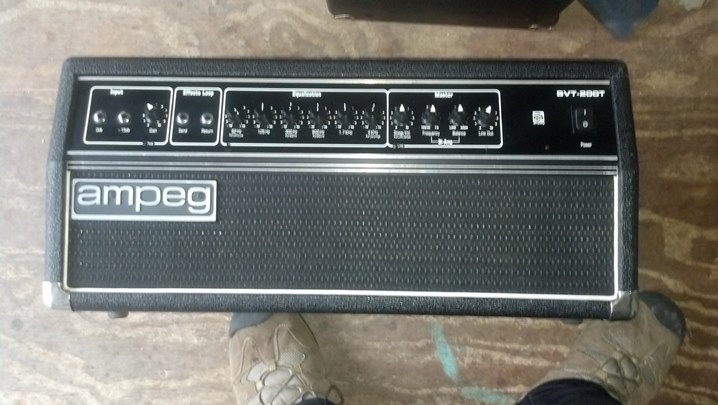
These units are highly regarded by many bass players.  Some consider them to be an equal to the tube-based models in the realm of versatility and sound.  And they are sure a lot lighter to carry around!

02SVT line outs
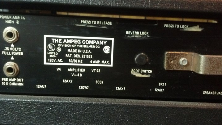
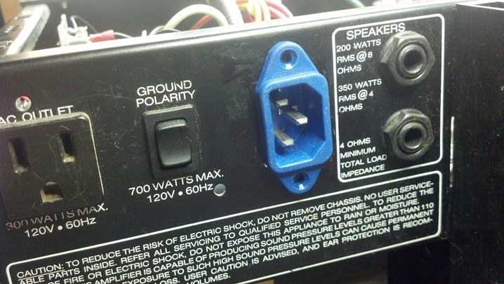
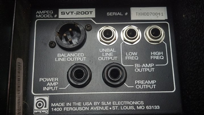
The rear panel is straight forward, with everything you need for a decent bass amp setup.  More goodness from St. Louis Music Electronics!

03SVT amp1
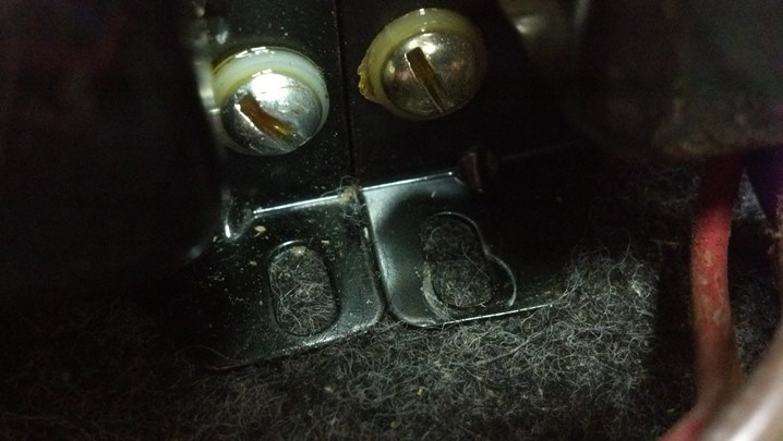
Inside, we have the interface to the front panel and some power transistors.  The unit with two flag terminals is a thermal switch that opens when the heat sink gets too hot.

04SVT amp2
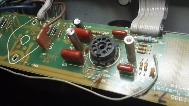
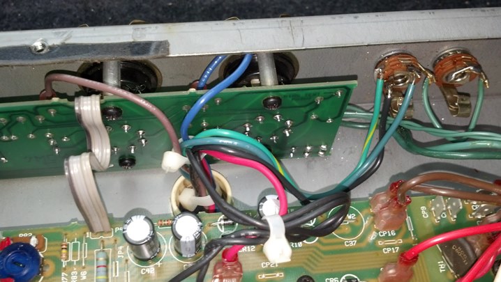
Here we have more power transistors and the driver transistor pairs.

05SVT amp3
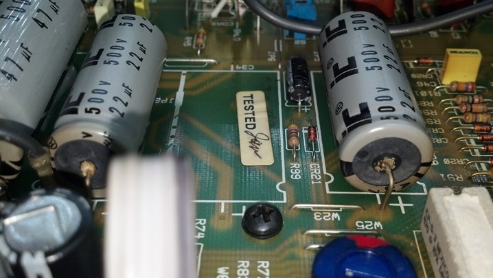
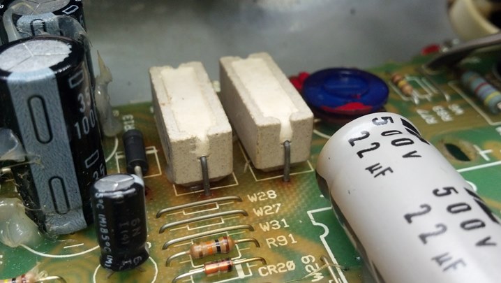
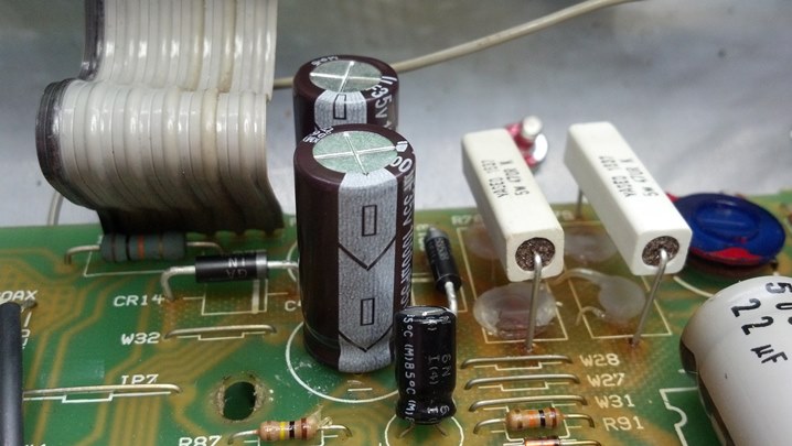
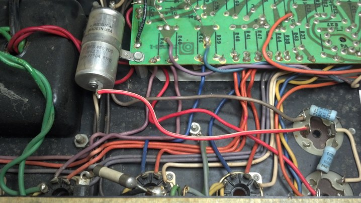
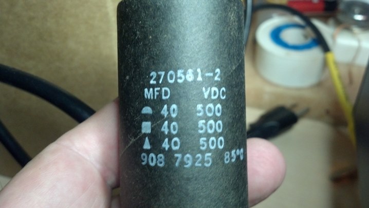
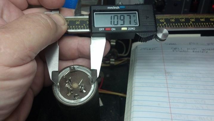
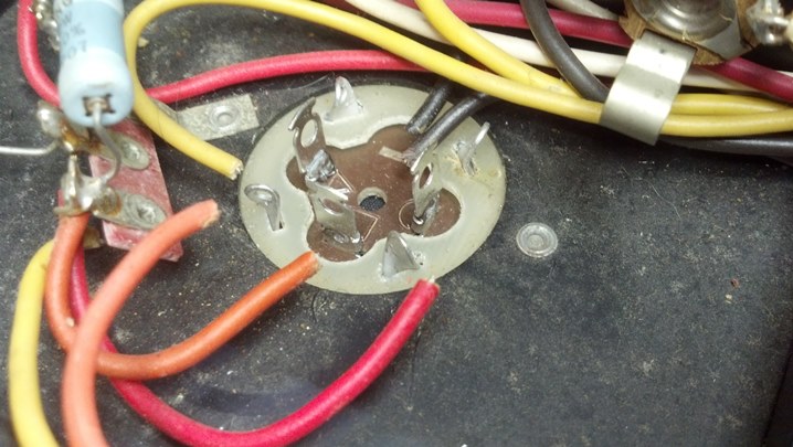
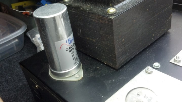
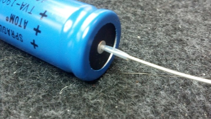
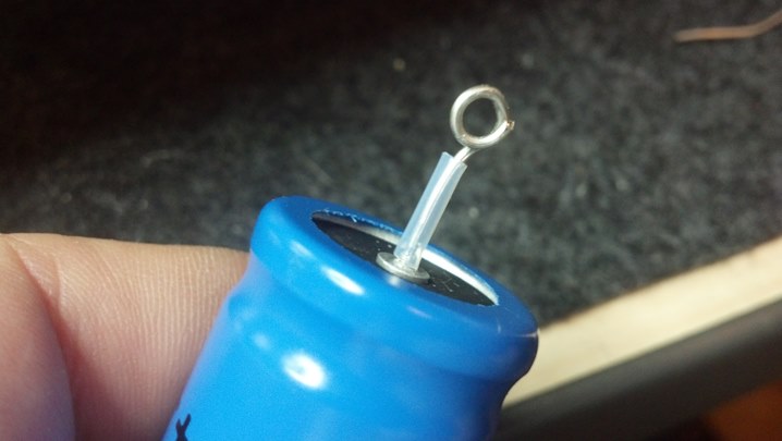
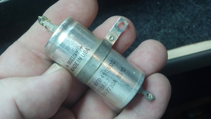
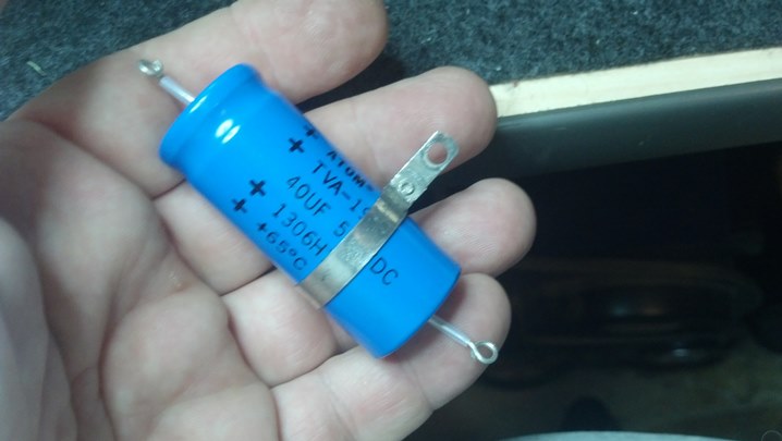
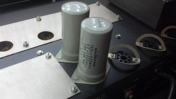
Power supply capacitors and the choke are found on this end of the board.

06SVT amp4
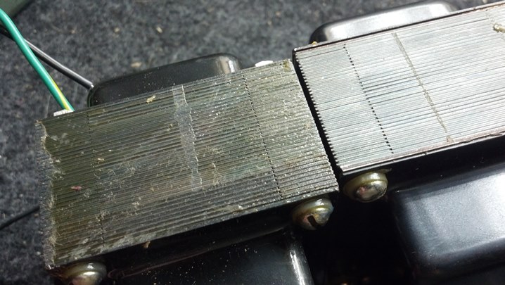
The power transformer is bolted here, and the input protection circuit board is mounted on the side of the chassis.

07SVT fp1
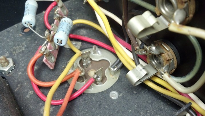
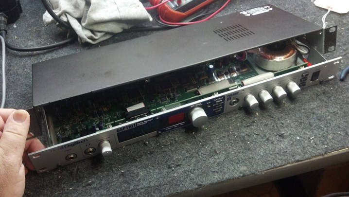
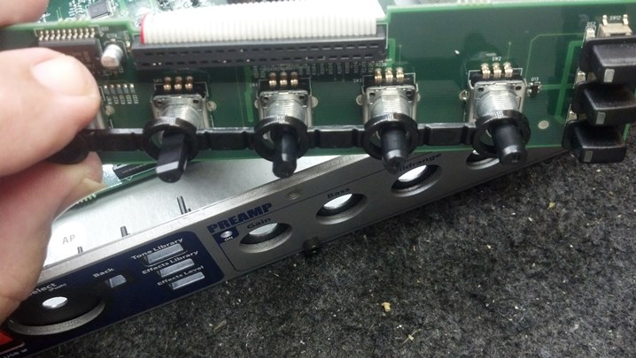
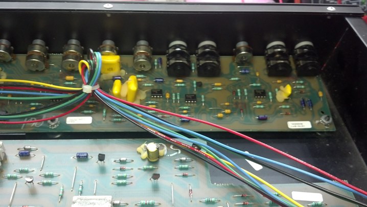
Input jacks and controls are found in this view, facing the back of the front panel.

08SVT fp2
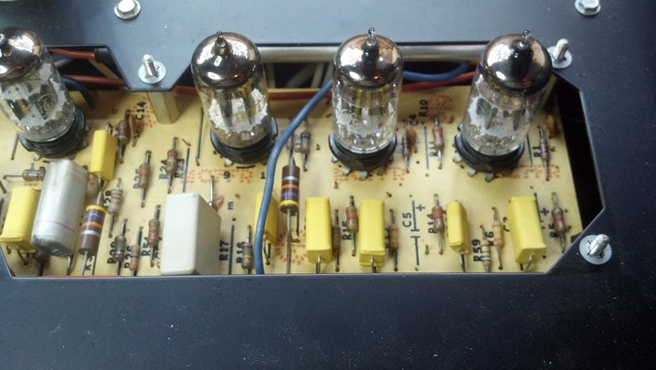
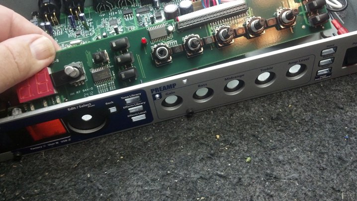
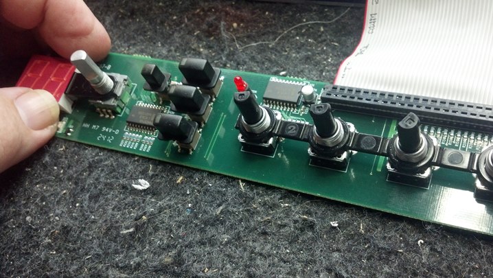
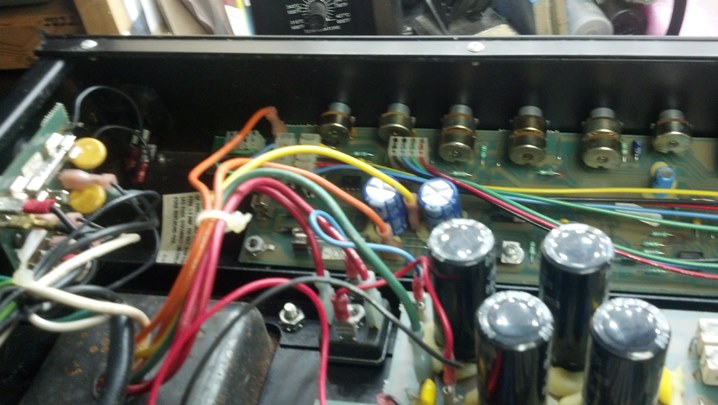
This is the rest of the front panel.  Note the big solid state rectifier for the power supply in the center foreground.

09SVT technology
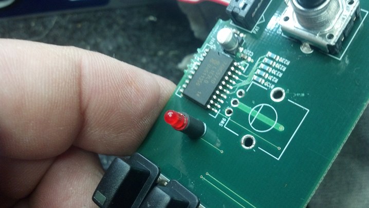
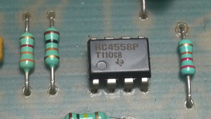
American-made Texas Instruments semiconductors are widely used throughout this unit.  Here is a preamp chip.

10SVT cord
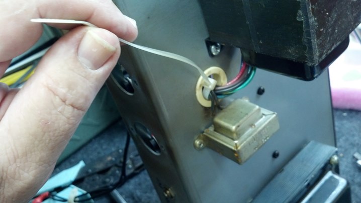
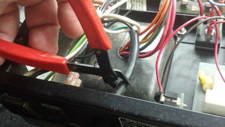
The original line cord is removed with a snip.  The wire remaining inside the chassis will be soldered directly to the IEC connector.  The big chunk of insulation will be removed.  The AC wiring will then be dressed in the same manner as the rest of the under-chassis wiring.

11SVT pwr in
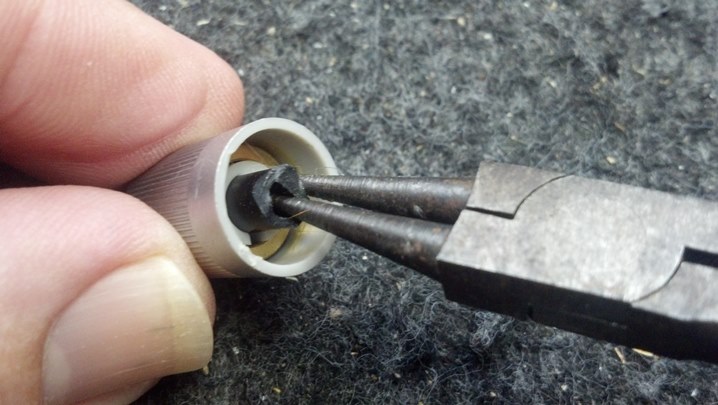
This blue IEC connector will be installed in the rear panel where the strain relief bushing goes.

12SVT hole dimsA rectangular hole will be cut to mount the IEC connector.  The pencil lines show up pretty well in this view.

13SVT magnetA magnet is positioned to keep the metal chaff from the sheet metal nibbler away from the electronics.

14SVT holeThis is the rough-cut hole.  More filing will gun-smith this into a rectangular shape.  Note the handle on the magnet visible through the rectangular hole.

15SVT trial fitHere, we are trial-fitting the IEC connector.

16SVT screwhole
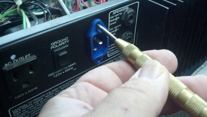
The location of the hold-down screws is marked with a center punch.

17SVT drillNow the holes for the screws are drilled, as you might have guessed.

18SVT trilobed scr
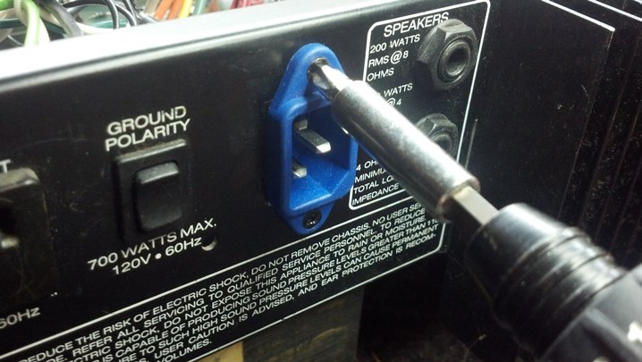
The machine screws are torqued, mounting the IEC connector in its new home.

19SVT magnetsThe magnets have really done their job.  None of these filings will be left loose inside the chassis!

20SVT wire prepThe cut ends of the power cord inside the chassis are stripped and tinned.

21SVT shrinkAs a nice touch, some heat shrink tubing of the correct color is slipped onto each wire.  Pure cosmetics!

22SVT solderThese are tacked into place for now.  Before the final joint is made, I’ll verify that the wires go to the right place!

23SVT shrink
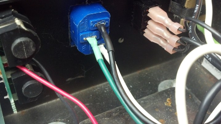
Wiring orientation is confirmed as correct!  The soldering was completed and the heat shrink tubing is shrunk into place.

24SVT line out test
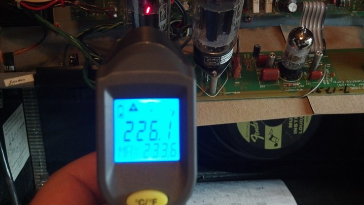
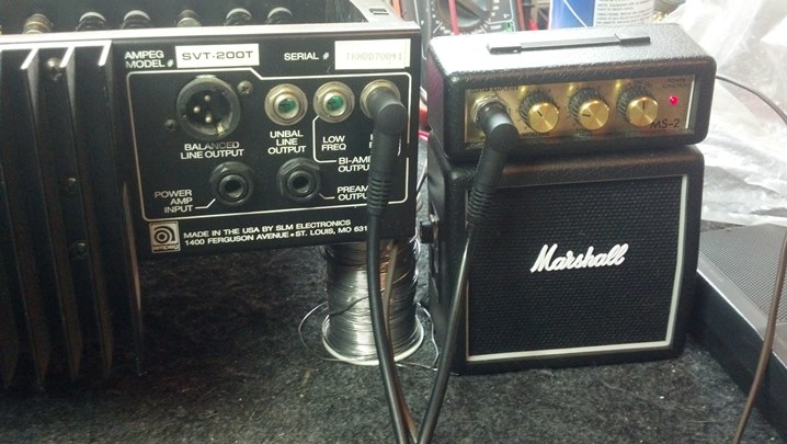
Here, I’m checking the functionality of the low-level signals to feed a bi-amp setup.  Note the Marshall Stack!

25SVT final test
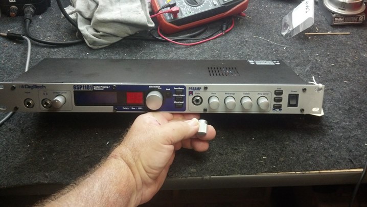
This unit is ready for the 21st century.  The modular cord makes setup and transportation more convenient.


Thanks for reading all the way to the end!

CONTACT – David Latchaw EE
281-636-8626

Fender Hot Rod Deluxe Car Wreck

This seasoned road warrior was happily touring and now was called up for recording duty.  However, at the final live set, the unit became very warm and the audio dropped way off.  Could the Unbrokenstring Crew work some magic to return this guy to the studio?

01HRD the patient1This unit has been in the shop once in the last year for a defective plate load resistor in the phase inverter.

02HRD nameplateApparently Fender received a batch of defective plate load resistors. The vendor corrected the problem, but a few of the amplifiers built with that particular batch of resistors have been in the field for years.

03HRD take apartThe circuit boards need to come loose to access everything. It turns out, the heat is coming from several sources.

04HRD probingThe schematic is on the monitor.  Unbrokenstring is trying out the Paperless Office Experience.

05HRD the problemThis is one of the open-circuited plate resistors on the phase splitter tube.

06HRD FixedHere is an NOS carbon composition resistor from stock.  It looks right at home in this amp.

07HRD caps1The real issue today is that the capacitors have begun to vent.  We need to address this with a recap.

08HRD caps2These units are all on the same circuit and are all the same age.  So they are all to be replaced.

09HRD heat1A previous non-Unbrokenstring repair around the low voltage regulator circuits fixed some burned circuit boards.

10HRD heat2These large resistors limit the Zener current. They are too close to the printed circuit board.

11HRD temp rangeThe capacitors will be replaced with units that have a higher temperature rating.

12HRD new partsHere, the Zener diodes and power resistors are spaced above the circuit board for better ventilation.

13HRD teflon tubingSome amp techs touch each cap with a screwdriver to discharge them. The positive lead carries about 400vdc and represents a safety hazard.  Those who ‘know’ will use a discharge wand on the tube socket or choke terminals to discharge this high voltage.  For the screw driver’s sake, we’re installing Teflon tubing on the exposed high voltage points.

14HRD plate resistor1We are changing out the plate load resistors.  All of the preamp tubes use a 100k resistor in the plate circuit.  This resistor is also part of the audio path e.g. the amplified signal appears on the plate end of this resistor, so we will benefit from modern 21st century components for duty in this part of the circuit.   Again, they are spaced above the circuit board to keep the body temperature (and noise) low.

15HRD plate resistor2More plate load resistor goodness…

16HRD input jacks1The plastic input jacks are replaced with American-made Amphenol units which are bolted directly to the front panel.

17HRD first testThe circuit boards are placed back into position and the unit is placed under test.  After an hour and a half of a four hour burn-in, the amplitude dropped off again.

18HRD power1Bias current climbed a few milliamps and could not be put back to normal. Here is a temperature reading at the base of one of the output tubes.

19HRD power2This is the temperature of the other tube base.  Obviously, the circuit is unbalanced now because the other tube is a lot hotter.  We will check the tubes again, but something else is happening here.

20HRD preampHere is the temperature of one of the preamp tubes.

21HRD transformersSurprisingly, everything returns to normal when the amp cools.  The chassis is on the bench now to take a closer look.  Something looks wrong with the output transformer.  Running the unit on the bench while applying a heat gun to the output transformer duplicated the problem!

22HRD disassembly againA new output transformer is still available from Fender!  Let’s substitute the new one and restart the test.

23HRD wires1The red and brown leads are the ends of the output transformer primary winding that are driven by the output tubes.

24HRD wires2The red wire is the center tap, which is fed high voltage.  The black wires connect the power supply choke into the circuit.

25HRD wires3The output windings of the output transformer go here.  Pay attention to the striped, unstriped, and black wires.

26HRD wires4All of the wires to the output transformer go through this TieWrap.  We’ll snip this to get it out of the way for now.

27HRD wires5Here are the output transformer leads.  Now, we unscrew the transformer from the chassis.

28HRD xformer1I compared the two transformers.  The bases are lined up, but the top is misaligned.  What the…?

29HRD xformer2Yes, the feet and bottom of the frame is aligned.

30HRD xformer3But the top of the lamination stack is definitely displaced on the top.

31HRD xformer4Here, the laminations are parallel, but the straight edge shows that the old transformer is definitely parallelogrammed.

32HRD Broken Glass1A phone call to the owner reveals that this amp was in a serious car wreck about five years ago.

33HRD Broken Glass2That wreck explains why the bottom of this amp is filled with broken safety glass.  The force of the car wreck deformed the output transformer.  I’m guessing that as the deformed transformer heated up, the internal insulation broke down somewhere because the windings were stretched by the deformed transformer.

34HRD new xformer1Let’s bolt down the new transformer.  Here, the leads are fished through the grommet in the chassis.

35HRD new xformer2A replacement TieWrap is installed in place of the old one.  The small transformer is the power supply choke.

36HRD new xformer3More TieWraps are applied to dress the leads in a manner similar to the original.

37HRD cleanup panelI’m pretty confident that the unit will work fine now!  Let’s put everything together, including all those knobs!

38HRD input jacks2Here are the new jacks.

39HRD new finalsThe new output transformer deserves a new set of tubes.

40HRD new preampThese preamp tubes were ordered at the same time.

41HRD biasA one ohm resistor in series with the output plate circuit allows us to directly read the idle current of the output tubes.  60mV corresponds to 60mA of bias current, exactly what Fender specifies.

42HRD lower temp1Another temperature check is performed after everything warms up.

43HRD lower temp2This little thermometer came from Harbor Freight.  It works surprisingly well for a $20 infrared thermometer.

44HRD final final testWe are restarting the four hour test from the start.

45HRD happy ampIf you look closely, you can see a blue beam of electrons flying into the tube envelope through a small aperture in the plate.  These bottles are happy!

46HRD back homeThis road warrior has a new cover!

Listen to this amp in action at http://billybourbonmusic.com/ and support this artist!

Thanks for reading all the way to the end!

CONTACT – David Latchaw EE
281-636-8626


Ampeg V4B Bass Amp Refurbishment

This wonderful old Selmer-era Ampeg bass head was pulled out of its retirement in the closet and put back into service.  But it had a few issues to address, so that it could reliably pump out the tones that is the Ampeg Experience.


01V4B the patientThis unit appears to be absolutely factory stock.  The Houston humidity has had an effect on the aluminum faceplate.

02V4V rear pnl1Taking a tour of the rear panel, we see a bracket upon which the line cord may be wrapped.

03V4B rear pnl2The convenience outlet is a three-prong unit, which is nice.  The hum balance control adjusts the bias current in the output tubes to be the same.

04V4B rear pnl3Magnavox owned both Selmer and Ampeg for a while, if I recall correctly.  Note the tube layout information.

05V4B rear pnl4Here is the other bracket for the cord, and the output jacks and impedance switching.

06V4B cordDude, are you still smoking?

07V4B internals1This is a nice intersection between hand wiring and the use of an etched circuit board.

08V4B internals2This cap and the bleeder resistors are slated for replacement.

09V4B cap1Yes, you can still get multi-section capacitors if you shop diligently.

10V4B cap2The prongs of the new capacitor need to fit in the slots in the chassis.

11V4B cap3There is plenty of height inside the chassis, but it doesn’t hurt to document what we have.

12V4B cap4Likewise, we’re documenting what we have.

13V4B cap1Here is the new multi-sectioned filter capacitor and the hole where it goes in the background.

14V4B cap2The outer can of all of the capacitors is isolated from the chassis, so these green fiberglass spacers are used under the capacitor.

15V4B cap3I think we’re done here!

16V4B cap4The new cap looks nice on the top of the chassis.

17V4B cap3The axial filter capacitor will be replaced with this part.  I am forming the leads to appear in a manner similar to the original part, seen above.  A little Teflon insulating tubing helps keep the electricity under control.

18V4B cap4Wires will be attached to the terminals, so the leads are formed into a loop to accept the wires.

19V4B cap5The wire bending is done with a hand-tool called “chain nose pliers.”

20V4B cap6The original part has a mounting ring around it.  We will need to recycle this mounting scheme to maintain originality.

21V4B cap7The ring is off!  I was a little concerned that I would mess it up, but a little heat was all it took.

22V4B cap8Here is the original mounting ring applied to the new capacitor.

23V4B cap9The ring can slide around just a little bit to give us a nice-looking mounting solution.

24V4B cap10And here we are, all wired up and ready to go back to work.

25V4B good capsThese guys have been replaced recently, and they check out as new.  So, they will remain in service.

26V4B controlsSome of the front panel slide switches were dirty, so some cleaner and lubricant were sprayed into them.

27V4B top1Now that the caps are changed out, let’s look at the top of the chassis.  The output transformer and output tubes are on the left side of the chassis.

28V4B top2The preamp tubes and power transformer are at the right end of the chassis.

29V4B top2detail1The open areas around the tube sockets are a nice touch.  The chassis is steel and very stiff, even with the relief.

30V4B top2detail2More low and medium voltage goodness at the other end of the slot.  Nearly every schematic test point is accessible from the top of the unit without turning it over on the bench.

31V4B Magnavox 12DW7This 6K11 Compactron tube tests very good, with each of the sections closely matched to the others.  Good News!

32V4B inputjax1The input jacks were corroded, so these were changed out with new Amphenol units.

33V4B inputjax2Here is the inside-the-chassis view of the new jacks.

34V4B indicator1The neon indicator for the AC power was functional, but the indicator for the high voltage was not.

35V4B indicator2So, this neon indicator will take its place.  The mounting hole is the same size, but the new part is chrome.  What to do?

36V4B indicator3We scrubbed the chrome ring with steel wool, then applied several coats of black polyurethane paint to the bezel.

37V4B Indicator4Here are both indicators.  The high voltage is amber, and the AC indicator is red, as it was when the amp came from the factory.  The colors are a bit messed-up because of the jpeg processing in the camera…  looks good in Real Life!

38V4B Happy CustomerAnother happy customer picks up his finished bass head!

Thanks for reading all the way to the end!

CONTACT – David Latchaw EE
281-636-8626

Digitech GSP1101 Effects Processor Repair

A frantic spouse called to explain that she was vacuuming and hit this ‘thing’ and broke this little piece off it.  Could I fix it before her husband found out?  The Unbrokenstring Crew to the rescue again!

01GSP brokenThe gain knob on this unit is a rotary encoder.  This component is available from several vendors.

02GSP what to doShe kept the knob, which is GREAT news, because although the rotary encoder is available, the knob is not.

03GSP salvage knobThe remains of the shaft of the rotary encoder was removed from the knob.  So far, so good.

04GSP opensesameLet’s get to work replacing the broken rotary encoder.

05GSP knobs offAs is the usual case, all the knobs come off first.

06GSP board looseThe circuit board lifts away easily.

07GSP spacer1These cool little plastic spacers set the geometry of the rest of the buttons and controls.

08GSP spacer2We will put this piece away somewhere safe while work elsewhere continues.

09GSP remove oldTo minimize the stress on the circuit board while removing the old component, the body of the broken rotary encoder is cut away from the component leads at an angle perpendicular to the circuit board.

10GSP part goneWith the component cut away from the circuit board, de-soldering the legs becomes trivial.

11GSP clear backThe component legs are gone.  This is a high-quality circuit board, double-sided copper and plated-thru holes.

12GSP clear frontBoth sides of the circuit board are cleaned up.

13GSP new partHere is the new part, ready to be soldered onto the circuit board.

14GSP reassemble1We are ready for reassembly.  That plastic spacer is re-installed as it was before.

15GSP reassemble2The cable carries all the signals back and forth to the front panel.  I like this bit of orgami.

16GSP reassemble3The circuit board is held in place by the bodies of the controls, which are in turn bolted to the front panel.

17GSP knobs onEverything is back together, ready for testing.

18GSP power onThis looks good!  While we were at it, we will do a factory reset.

19GSP final testNow, everything is as it once was.  And the husband was scolded for leaving his toys on the floor, where she could hit them with the vacuum.  Maybe I could sell him a rack case?

Thanks for reading all the way through!

CONTACT – David Latchaw EE
281-636-8626

Vintage Boss Chorus Ensemble Pedal Refurb

Wonderfully-preserved from the era when one could still see Stevie Ray Vaughn perform live, we find a Boss Chorus Ensemble pedal that had been stored for decades.  In the years since, many advances in computer sound modeling has made an infinite universe of tone available to the aspiring guitarist.  However, there is just ‘something’ about the Real Thing.  The owner wanted this wonderful piece of history refurbished and placed back into service.

Years of storage in the high Houston humidity has taken a toll on the outside.  What’s up with those screws on the HIGH/LOW input level switch?

Forget that stuff made in China.  This is the real thing, from Japan!

Since when was an electric guitar considered “HOUSEHOLD ELECTRONIC EQUIPMENT”?

The nomenclature for the input and output jacks appears on the top of the unit.

Let’s make a quick tour of the unit.  This is the left half of the front panel.

This is the right half of the front panel.

Several pictures of the circuit boards were made, to verify that the service literature used for this refurb matched reality.  This is the top half of the circuit board’s component side.

This is the bottom half of the component side of the circuit board.  Those fuses are on the AC output of the power transformer.

Most of the screws in the bottom of the unit were missing.  This unit was balancing on two feet.

The interior layout is actually pretty cool, well-representing the line-powered Japanese gear of the period.

I’m going back through and documenting where the various wire colors go.  Note that the wires are just tacked to brass eyelets swaged into the circuit board.  The AC power wires get their own riveted tie points.

Looking closely at the wiring.

Wiring closeups.

More wiring closeups.  This is factory wiring, I believe.

More colored wires.

The black ground wire gets its own lug.

A quick jab of the soldering iron frees the circuit board from the wiring harness.  All passive components were checked and anything that was out of spec was replaced.  Most of the forty-year-old electrolytic capacitors were replaced.

The outer jacket of the AC cord dry-rotted.  This looks gnarly, but the inner insulation seems to be fine.

A new cord is identified with the same outer diameter and wire gauge.

The blue and green wires are the input to the primary wiring of the power transformer.  Note the cable clamp pressed into service as a strain relief for the power cord.

The old cord is gone.  We can keep the cable clamp and move it to the new cord set.

This grommet would not ‘fly’ with UL today, but was fine for the 1980s.  This will be used again.

The new cord is stripped back.  Note the authentic cotton filler.

The cotton mop is trimmed away and the original cable tie is slipped on the new cord.  Next comes the grommet.

The original strain relief was retained.  The white and black wires were later terminated to the green and blue wires seen above.

Both foot switches were ruined.  Out they come!

This is the wiring side of the original ‘effect/bypass’ switch.

Out it comes.  The escutcheon is in rough shape.  Maybe we can freshen it up.

Here we’re trying to salvage some of the original hardware.  A sideways blow the old foot switch damaged the threads.

Here is the wiring side of the chorus/vibrato switch.  This switch was intermittent.

Rather than desolder the wires, I trimmed them off square.  They will be stripped and re-terminated on the new switch.

A pair of DPDT foot switches will adequately replace the foot switches in this unit.

The original trim nuts were in good shape and will be reused, to preserve the original appearance of the unit.

Now let’s move our attention to the potentiometers and switches in this unit.

The nuts were rusty but in good shape otherwise.  Here, one of my deep sockets with the felt cover is used to remove the nuts.  The felt prevents the socket from marring the soft aluminum face plate.

Note the letter “C” after the first line of text.  This denotes a reverse taper pot, used for the vibrato rate control.

Vibrato depth control is a linear taper control, thus the letter “B.”

The chorus intensity control is a linear control as well.

And who would have guessed that the level control was an audio taper potentiometer?

Each potentiomenter was flushed with Blue Shower.

A blast of Rid-Ox really does the trick on dirty contacts.

Some synthetic lubricant keeps the shaft turning smoothly.

Until I get the air compressor line plumbed to the bench, Air In A Can will have to do to dry everything out.

This process leaves everything spotless and clean, inside and out!

A soft tooth brush works well with the crinkle finish paint used on this unit.

The toothbrush cleans the grooves around the indicator lamps.

A lint-free cloth carries away four decades of gunk.

Before going further on the outside, we need to get under the front panel.

With the potentiometers and switches removed, the aluminum panel lifts right out.

Placing the aluminum panel flat on a carpeted surface, gentle pressure will allow us to remove dents.

With the front panel set aside, we can turn our attention to the power switch.  This switch needs cleaning as well.

It gets a treatment similar to the one given the potentiometers.  This is much better!

With the individual pieces reconditioned, it’s time for reassembly.

Controls and switches were installed and wired.  The wiring harness was returned to its factory layout.

We’re starting the process of restoring all the connections made by the colored wires.

Testing was performed with a sheet of cardboard between the circuit board and the metal chassis.

I spotted these parts at a local hardware store.  These screws and bumpers are perfect for replacing the rubber feet.

This guy is ready for another four decades of vintage guitar sound.  This unit sounds AMAZING!

Thanks for reading all the way through!

CONTACT – David Latchaw EE
281-636-8626