JR Beck Six String Bass Blend Pot Adventure

Billy said that he really liked this bass, but the blend pot was coming loose and something electrical was intermittent inside the instrument. Could The Unbrokenstring Crew look it over and make it stage-worthy again?

In literary circles, the term “vanity publishing” is often applied to authors who self-publish their own works. The JR Beck line is a ‘vanity-built’ line of musical instruments, wherein an individual approaches an instrument manufacturer to build instruments under a new name. This bass likely came into the world as part of a contract with a Korean manufacturer.


The neck is straight and the frets are level.  This is a player’s six string bass.


The head stock shape reminds me of an Ibanez profile.


The Grover tuners are really nice.


Someone has been here before.  This screw is too long for the hole.


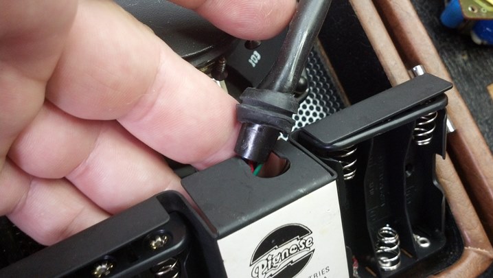
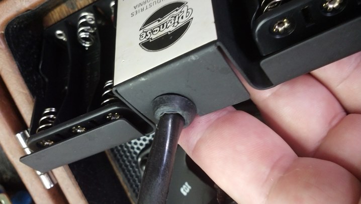
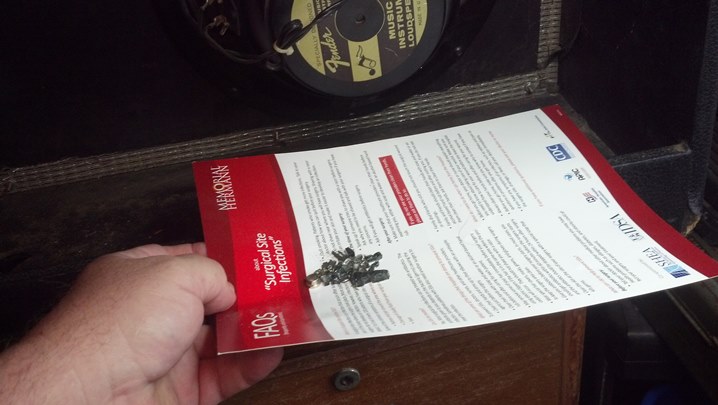
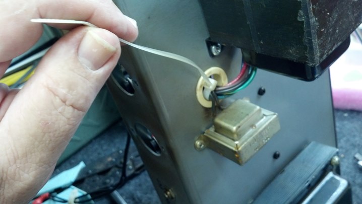
Just how deep does the hole need to be?  It needs to be THIS long.


We will bore this hole down to the tape go get the length we want.


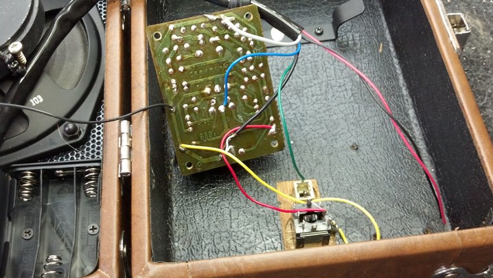
I can find no markings on the preamp electronics.  The rest of the wiring is a mess around the blend pot.


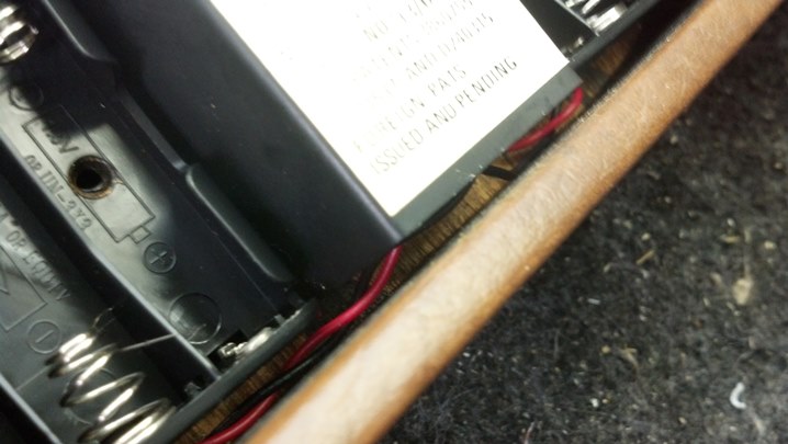
The duct tape did NOT come from Korea.  Why not get someone who can do this sort of work cleanly, like me?


The blend pot is a hack job.  The rest of the wiring is probably as it was from the factory.


Use more solder if you don’t solder it right the first time.  The solder has actually flowed inside the unit and mechanically interferes with the rotation of the wiper in one of the sections of the control.


We’ve removed the wires from the blend pot.  The cables with the green and yellow jacket come from the pickups. The cable with the white jacket wire goes to the active electronics.


Some RTV was used in an attempt to stabilize the front face of the blend control and keep it from moving when the knob was twisted.  What a mess.


As the control moved around, it scored up the wood body of the bass.  No pick guard on this unit.


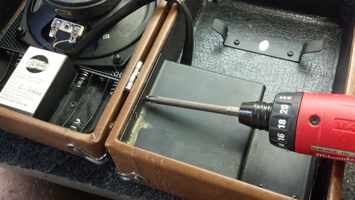
To stabilize the wood and prep to mount a new control in a stable manner, a Forstner bit is employed to create a flat-bottomed ‘spot face’ in the wood cavity.  There is some risk of penetration, so we’re going slowly at this point.


A flat-bottom hole is bored without incident.  A steel washer will be epoxied into the body to fully-support the new blend pot.


The new blend pot comes with a couple of flat washers.  I’ll use a lock washer and another nut to set the height of the control so that the knobs are all installed at the same height on the face of the guitar.


A blend pot is a pair of “M” taper potentiometers, which allow one pickup to be faded out as the other side gets louder.  As the control reaches each limit of its travel, the other pickup is electrically ‘cut out’ of the circuit.  In a way, it acts as a selector switch at each end of the travel, with a continuous blend of the two signals in between.


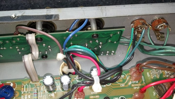
The cross wiring is done with solid 20AWG copper covered with Teflon tubing.  The pickups are wired on the end.


This control has an index pin.  We will cut a slot in the steel washer to ‘catch’ this index pin and hold everything in place.


Initial tests showed that the signals from both pickups were literally ‘grounded’ when the control was set to either limit.  We need to install range-limiting resistors to each end of the controls so that the selected pickup is not grounded at the end of the potentiometer travel.  This is a blend pot, not a kill switch, after all.


It is an easy task to break the connection to ground and install a fixed resistor.  The proper value depends, in part, on the internal DC resistance of each pickup.  It will be easier to discover the proper value empirically.


The box with all the switches is sometimes called a ‘design box.’  The proper name is a ‘resistance substitution box.’  Various values of resistors are switched into the circuit until the desired result is obtained.  Here, we are choosing a resistor value for one side of the blend pot.  Too low a value attenuates the signal.  Too high a value causes hum.


Here is the fixed resistor for this side of the blend pot.  Note the use of the Teflon tubing to keep the signals under control.


Here is the new control installed in its new home.  I am satisfied with the electrical results of this experiment.


The original knob works nicely with the new control.  Note that the knobs are all the same height off the body of the bass.  Another thing I like about this bass is, look at that massive bridge saddle and end block!  The Koreans really know how to do it right.


Jacob takes the finished bass for a spin.  He wants one!

Thanks for reading all the way to the end!

CONTACT – David Latchaw EE
281-636-8626

Sovtek Small Stone Pedal Refurb and Update

The modulation rate control on this wonderful Sovtek Small Stone phaser effect pedal had broken. While the unit is in the shop, could the Unbrokenstring Crew also add a 21st century DC pedal power jack to the unit?

Like a message in a bottle, this pedal has the look and feel of a relic from another planet. Even the switch looks like alien technology.

Removing the top cover reveals a heavy steel plate that holds the major components.  Look at the LED holder!

The control for the phase modulation had disintegrated.  Not much was left holding the shaft in place.

The back side of the modulation control was not out of the ordinary beyond the Cyrillic alphabet. Perhaps it could be rebuilt using parts from another similarly-sized potentiometer.

We have removed the old potentiometer from the circuit.

The tabs on the back cover of the potentiometer can be peeled back in order to disassemble the unit.

Interestingly, the internals of this control are completely different than what we might expect from a domestic control.  This potentiometer is a ‘reverse audio taper’ component.  The Russians achieved this by mounting the resistive element on the opposite side of the main wafer of the control, effectively reversing the direction of the taper.

So, it appears that we need to find a control that is close to the physical size of the old part, so we can reuse the knob.

We are working in millimeters here, in case you are wondering.

An aluminum bushing allows this smaller shaft to fit in the Russian knob.  Perhaps we have another degree of freedom in our search for a proper replacement.

This bushing can be removed…  a good thing that will allow us to do some gun-smithing if we need to do so.

The knob is not quite big enough to allow a quarter-inch shaft to be substituted.

So, we located a reverse audio taper control custom-designed for Neve recording consoles.  Yeah, I got connections.

This part has an appropriately-sized shaft that will permit us to use the original knob.  Good news!

The new control is wired into the circuit in the same manner as the old one.  Teflon spaghetti tubing handles the high-temperature insulation duties here.

These little spacers were rattling around in the enclosure after the circuit board was removed.  Where do these go?

Turns out, they are spacers that go on top of the cast bosses in the bottom of the original box.

The new power jack is mounted and wired into place, along with new steel Switchcraft in and out jacks.

The whole arrangement is now fitted back into the case.

An internal nine volt battery is used for powering this unit for checkout.

We have a winner!  Time to tighten down the screws and button this unit back up.

Here is the top cover with the new control installed.

The case cover is now back on.

The owner wanted to leave no question regarding whose pedal this was.  Mine!!!  Mine!!

Thanks for reading all the way to the end!

CONTACT – David Latchaw EE
281-636-8626


Kurzweil K2500XS Synth Repair and Recondition

The youth worship leader called The Unbrokenstring Crew, having exhausted all other avenues available to him to get their synth repaired.  Could we step up to the plate and fix the various issues with this unit?

If you look closely, you will see a bit of green tape on the E key just above middle C.  That key plays loudly, or not at all.  There is no in-between, which is a problem while playing an offeratory.

Houston, we have a problem.  These batteries have taken their leaking game to a whole new level.

Fortunately, this battery box can be replaced.  But how much other stuff has been contaminated with electrolyte?

We need to split the case open to look at the wiring and circuit boards.

These screws hold the key bed in place.  This unit is so heavy that I decided to get some of these out while I was here.

This is what the inside of a synth looks like.  The battery box is to the left of center of the picture.  Everything is wet.

The ‘green tape’ issue is resolved by disassembling the key bed.  Out it comes, and it is heavy!

The screws holding down the pitch wheel assemblies are located on the bottom of the chassis.  This allowed all the battery electrolyte to be neutralized and cleaned out.

This key bed is from Fatar.  It is ‘semi-weighted’ and, to me, feels just like a real piano.

The key bed is tilted up to gain access to the bottom of the assembly.

I labelled these two ribbon cables B for bass and T for treble.  This corresponds to the left and right half of the keyboard, respectively.

These short jumpers go between two long circuit boards.  Note the white zero-ohm jumpers on the PCB.

Now we remove a whole bunch of screws to gain access to the other side of these circuit boards.

The long thin circuit boards are now free from the key bed chassis.  We see the objective of our mission!

These rubber strips are push buttons that close a pair of electrical circuits when a key is depressed.

There are two push buttons per key.  One button plunger is longer than the other.  When a key is depressed, the amount of time between one button and the other is used to derive velocity information for that note.

And here is our ‘green tape’ problem.  The longer button is torn, so the keyboard scanner only saw the shorter switch closure.  In a normally-operating keyboard, the longer button closes first, followed by the shorter one.

New keypad strips are available for this unit.  After inspecting the entire keyboard, I replaced two of the keypad strips for the octaves around middle C.

All of the strips were removed and the circuit board cleaned.  Note the pairs of carbon contacts on the PCB.

The key strips must fit securely in a precise orientation.  Note all the little alignment nubbins fitting into the PCB holes.

The key bed is ready to be reassembled.  Note the black plastic strips that serve as spacers between the metal cabinet of the key bed and the circuit boards.

This is the treble circuit board going back into the unit.

All those little screws seen earlier are re-installed.

The small ribbon cables is reinstalled.  Those big ribbon cables go back on next.

This is actually a ground conductor for the pitch wheel assembly.  I found it easier to reinstall the pitch wheel assembly now, before the key bed is placed back into place.

Some of the keys have an audible squeak when they are depressed.  OK, let’s fix this too!

I’ve modified a bamboo chop stick to reach into the center of the spring, allowing me to unhook the bottom of the spring.

Springs for the white keys are on either side of the spring used on the black keys, seen in the center.

Once the spring is removed, the key can be un-clipped from its hinge.

Very super-secret, highly-technical precision formulated compound is used to lubricate felts and friction points here.

A little bit of the lubricant is sparingly applied to where it needs to go to kill the squeaks.

The long tab actuates the weighted action of each key, giving this key bed its semi-weighted feel.  The shorter tab actually depresses the rubber key pad strip switch seen earlier, to signal the synth to make a sound.

Dr. Shoen gives the completed synth a trial run in piano mode.  He is very pleased with the keyboard action.

Jacob explores the synth presets.  I think everyone is satisfied with the repair!

Thanks for reading all the way to the end!

CONTACT – David Latchaw EE
281-636-8626

Pignose 7-100 Mini-Amp Refurb

This battery-powered portable amplifier is a novelty item seen in offices, bedrooms, and showrooms around the country.  This little guy doesn’t work anymore.  Could the Unbrokenstring Crew make it work again?

01PIG the patientThe pig’s nose is the on-off/volume control.  The input jack is just below the nose.

02PIG insideInside, we find a loudspeaker and battery box on the left, and the electronics and some cord storage on the right.

03PIG missing nutThis nut is missing.  Oh boy, this is Big Trouble in Little China.

04PIG acid everywhereThe cover over the electronics shows signs of corrosion, probably from battery acid.

05PIG found nutGood news!  We found the missing nut.

06PIG jacksThis panel is on one side.  Surprisingly, the power jack is ‘old technology’ and probably should be the same connector as seen on effect pedals.  But, hey, they didn’t ask me.

07PIG nameRankSerialThis metal piece secures the battery boxes in place.  Name, rank, and serial number please.

08PIG new bat boxThe original battery box was trash, so these units were procured.  Six batteries give us nine volts.  These x3 packs are necessary to fit into the space provided.

09PIG acid here tooCaustic chemicals from the leaking batteries were conducted, via capillary action, over to the amplifier side of the box.  A new pair of red and black wires were fished through the umbilical, replacing the corroded wires.

10PIG wired boxesHere, the new battery boxes are wired into the unit’s harness.

11PIG fitting boxesThe battery boxes rest on a metal bracket, which also serves as a noise shield over the volume control and input jack.

12PIG Strain reliefThis grommet serves as a strain relief for this end of the umbilical cable.

13PIG looking goodThis pic just shows how the leads are dressed. This unit is small, and the wires need to go into their correct places in order to close the unit up when we’re through.

14PIG watch lead dressThese red and black wires can be pinched between the case and the metal plate, so they need to be pulled up and out of the way before the screws are tightened down.

16PIG clean ampWe find the preamp and amp in the other side of the unit. The small assembly seen at the bottom is back side of the power jack and the ‘preamp out’ jack.

17PIG reinstall ampThis assembly was covered with caustic chemicals from the leaked batteries.  Miraculously, these transformers were not damaged.  Everything cleaned up very well.

18PIG cover onThis cover shields the amp and jacks.  We’re done here.

19PIG batteriesA fresh set of batteries and a twist of the knob puts this unit back on the air.  Time to call the customer!

Thanks for reading all the way to the end!

CONTACT – David Latchaw EE
281-636-8626

Fender Hot Rod Deluxe Car Wreck

This seasoned road warrior was happily touring and now was called up for recording duty.  However, at the final live set, the unit became very warm and the audio dropped way off.  Could the Unbrokenstring Crew work some magic to return this guy to the studio?

01HRD the patient1This unit has been in the shop once in the last year for a defective plate load resistor in the phase inverter.

02HRD nameplateApparently Fender received a batch of defective plate load resistors. The vendor corrected the problem, but a few of the amplifiers built with that particular batch of resistors have been in the field for years.

03HRD take apartThe circuit boards need to come loose to access everything. It turns out, the heat is coming from several sources.

04HRD probingThe schematic is on the monitor.  Unbrokenstring is trying out the Paperless Office Experience.

05HRD the problemThis is one of the open-circuited plate resistors on the phase splitter tube.

06HRD FixedHere is an NOS carbon composition resistor from stock.  It looks right at home in this amp.

07HRD caps1The real issue today is that the capacitors have begun to vent.  We need to address this with a recap.

08HRD caps2These units are all on the same circuit and are all the same age.  So they are all to be replaced.

09HRD heat1A previous non-Unbrokenstring repair around the low voltage regulator circuits fixed some burned circuit boards.

10HRD heat2These large resistors limit the Zener current. They are too close to the printed circuit board.

11HRD temp rangeThe capacitors will be replaced with units that have a higher temperature rating.

12HRD new partsHere, the Zener diodes and power resistors are spaced above the circuit board for better ventilation.

13HRD teflon tubingSome amp techs touch each cap with a screwdriver to discharge them. The positive lead carries about 400vdc and represents a safety hazard.  Those who ‘know’ will use a discharge wand on the tube socket or choke terminals to discharge this high voltage.  For the screw driver’s sake, we’re installing Teflon tubing on the exposed high voltage points.

14HRD plate resistor1We are changing out the plate load resistors.  All of the preamp tubes use a 100k resistor in the plate circuit.  This resistor is also part of the audio path e.g. the amplified signal appears on the plate end of this resistor, so we will benefit from modern 21st century components for duty in this part of the circuit.   Again, they are spaced above the circuit board to keep the body temperature (and noise) low.

15HRD plate resistor2More plate load resistor goodness…

16HRD input jacks1The plastic input jacks are replaced with American-made Amphenol units which are bolted directly to the front panel.

17HRD first testThe circuit boards are placed back into position and the unit is placed under test.  After an hour and a half of a four hour burn-in, the amplitude dropped off again.

18HRD power1Bias current climbed a few milliamps and could not be put back to normal. Here is a temperature reading at the base of one of the output tubes.

19HRD power2This is the temperature of the other tube base.  Obviously, the circuit is unbalanced now because the other tube is a lot hotter.  We will check the tubes again, but something else is happening here.

20HRD preampHere is the temperature of one of the preamp tubes.

21HRD transformersSurprisingly, everything returns to normal when the amp cools.  The chassis is on the bench now to take a closer look.  Something looks wrong with the output transformer.  Running the unit on the bench while applying a heat gun to the output transformer duplicated the problem!

22HRD disassembly againA new output transformer is still available from Fender!  Let’s substitute the new one and restart the test.

23HRD wires1The red and brown leads are the ends of the output transformer primary winding that are driven by the output tubes.

24HRD wires2The red wire is the center tap, which is fed high voltage.  The black wires connect the power supply choke into the circuit.

25HRD wires3The output windings of the output transformer go here.  Pay attention to the striped, unstriped, and black wires.

26HRD wires4All of the wires to the output transformer go through this TieWrap.  We’ll snip this to get it out of the way for now.

27HRD wires5Here are the output transformer leads.  Now, we unscrew the transformer from the chassis.

28HRD xformer1I compared the two transformers.  The bases are lined up, but the top is misaligned.  What the…?

29HRD xformer2Yes, the feet and bottom of the frame is aligned.

30HRD xformer3But the top of the lamination stack is definitely displaced on the top.

31HRD xformer4Here, the laminations are parallel, but the straight edge shows that the old transformer is definitely parallelogrammed.

32HRD Broken Glass1A phone call to the owner reveals that this amp was in a serious car wreck about five years ago.

33HRD Broken Glass2That wreck explains why the bottom of this amp is filled with broken safety glass.  The force of the car wreck deformed the output transformer.  I’m guessing that as the deformed transformer heated up, the internal insulation broke down somewhere because the windings were stretched by the deformed transformer.

34HRD new xformer1Let’s bolt down the new transformer.  Here, the leads are fished through the grommet in the chassis.

35HRD new xformer2A replacement TieWrap is installed in place of the old one.  The small transformer is the power supply choke.

36HRD new xformer3More TieWraps are applied to dress the leads in a manner similar to the original.

37HRD cleanup panelI’m pretty confident that the unit will work fine now!  Let’s put everything together, including all those knobs!

38HRD input jacks2Here are the new jacks.

39HRD new finalsThe new output transformer deserves a new set of tubes.

40HRD new preampThese preamp tubes were ordered at the same time.

41HRD biasA one ohm resistor in series with the output plate circuit allows us to directly read the idle current of the output tubes.  60mV corresponds to 60mA of bias current, exactly what Fender specifies.

42HRD lower temp1Another temperature check is performed after everything warms up.

43HRD lower temp2This little thermometer came from Harbor Freight.  It works surprisingly well for a $20 infrared thermometer.

44HRD final final testWe are restarting the four hour test from the start.

45HRD happy ampIf you look closely, you can see a blue beam of electrons flying into the tube envelope through a small aperture in the plate.  These bottles are happy!

46HRD back homeThis road warrior has a new cover!

Listen to this amp in action at http://billybourbonmusic.com/ and support this artist!

Thanks for reading all the way to the end!

CONTACT – David Latchaw EE
281-636-8626