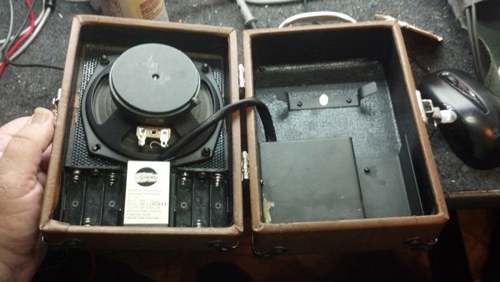
This seasoned road warrior was happily touring and now was called up for recording duty. However, at the final live set, the unit became very warm and the audio dropped way off. Could the Unbrokenstring Crew work some magic to return this guy to the studio?
 This unit has been in the shop once in the last year for a defective plate load resistor in the phase inverter.
 Apparently Fender received a batch of defective plate load resistors. The vendor corrected the problem, but a few of the amplifiers built with that particular batch of resistors have been in the field for years.
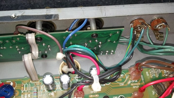
 The circuit boards need to come loose to access everything. It turns out, the heat is coming from several sources.
 The schematic is on the monitor. Unbrokenstring is trying out the Paperless Office Experience.
 This is one of the open-circuited plate resistors on the phase splitter tube.
 Here is an NOS carbon composition resistor from stock. It looks right at home in this amp.
 The real issue today is that the capacitors have begun to vent. We need to address this with a recap.
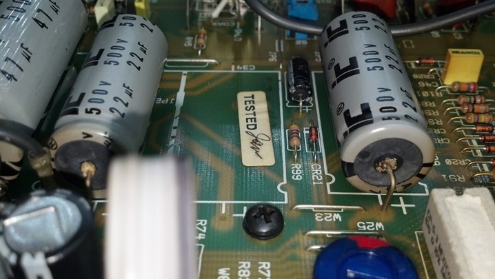 These units are all on the same circuit and are all the same age. So they are all to be replaced.
 A previous non-Unbrokenstring repair around the low voltage regulator circuits fixed some burned circuit boards.
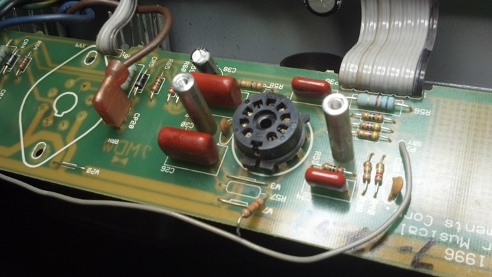
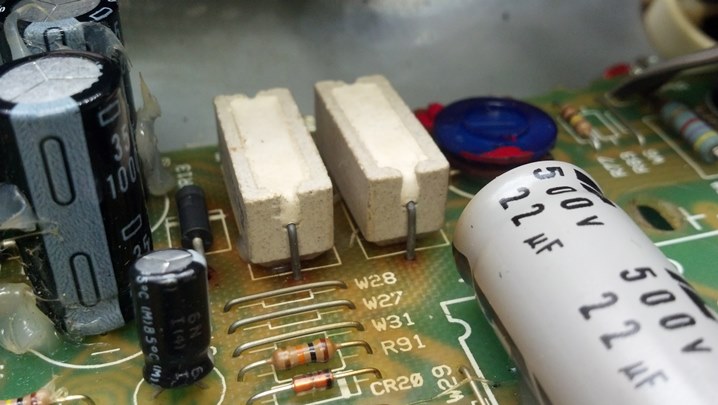 These large resistors limit the Zener current. They are too close to the printed circuit board.
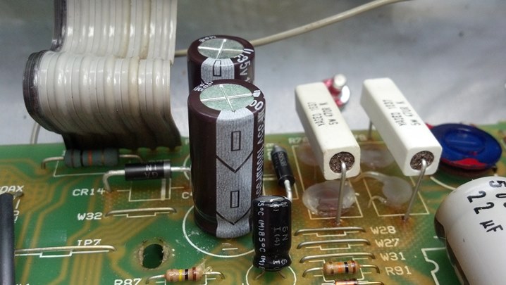
 The capacitors will be replaced with units that have a higher temperature rating.
 Here, the Zener diodes and power resistors are spaced above the circuit board for better ventilation.
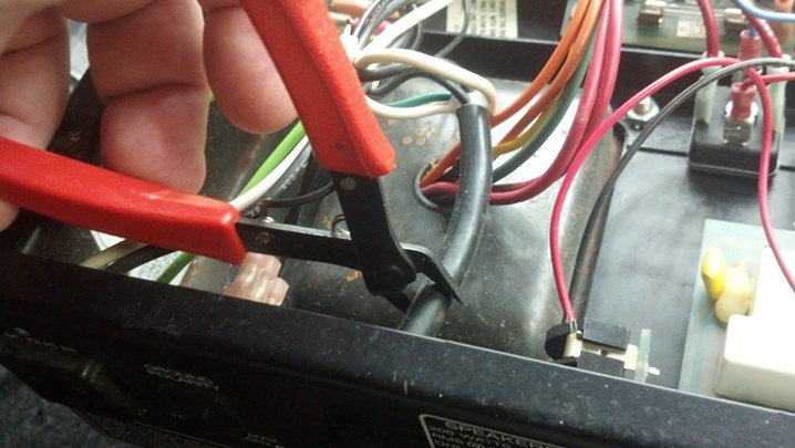
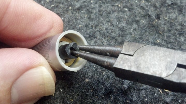
 Some amp techs touch each cap with a screwdriver to discharge them. The positive lead carries about 400vdc and represents a safety hazard. Those who ‘know’ will use a discharge wand on the tube socket or choke terminals to discharge this high voltage. For the screw driver’s sake, we’re installing Teflon tubing on the exposed high voltage points.
 We are changing out the plate load resistors. All of the preamp tubes use a 100k resistor in the plate circuit. This resistor is also part of the audio path e.g. the amplified signal appears on the plate end of this resistor, so we will benefit from modern 21st century components for duty in this part of the circuit. Again, they are spaced above the circuit board to keep the body temperature (and noise) low.
 More plate load resistor goodness…
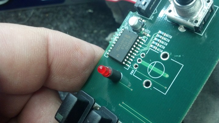
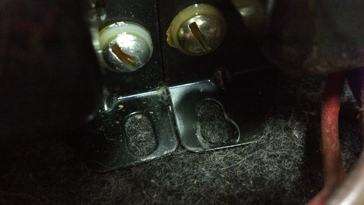
 The plastic input jacks are replaced with American-made Amphenol units which are bolted directly to the front panel.
 The circuit boards are placed back into position and the unit is placed under test. After an hour and a half of a four hour burn-in, the amplitude dropped off again.
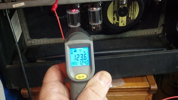
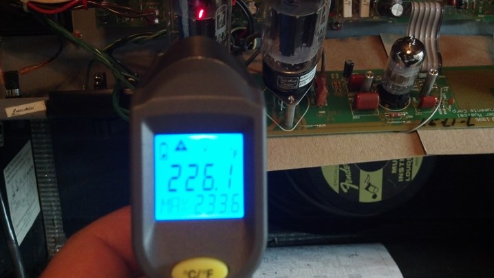 Bias current climbed a few milliamps and could not be put back to normal. Here is a temperature reading at the base of one of the output tubes.
 This is the temperature of the other tube base. Obviously, the circuit is unbalanced now because the other tube is a lot hotter. We will check the tubes again, but something else is happening here.
 Here is the temperature of one of the preamp tubes.
 Surprisingly, everything returns to normal when the amp cools. The chassis is on the bench now to take a closer look. Something looks wrong with the output transformer. Running the unit on the bench while applying a heat gun to the output transformer duplicated the problem!
 A new output transformer is still available from Fender! Let’s substitute the new one and restart the test.
 The red and brown leads are the ends of the output transformer primary winding that are driven by the output tubes.
 The red wire is the center tap, which is fed high voltage. The black wires connect the power supply choke into the circuit.
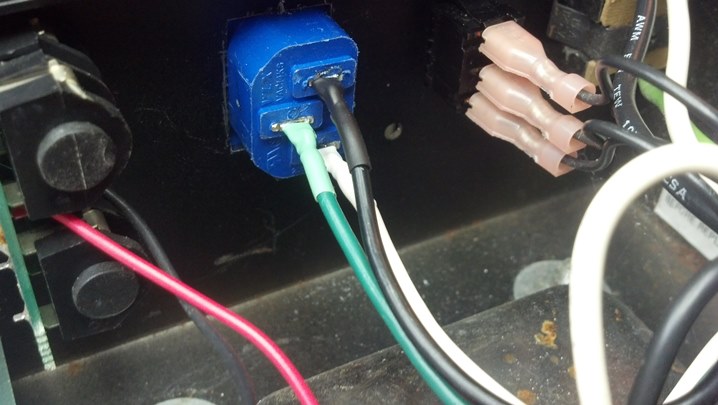
 The output windings of the output transformer go here. Pay attention to the striped, unstriped, and black wires.
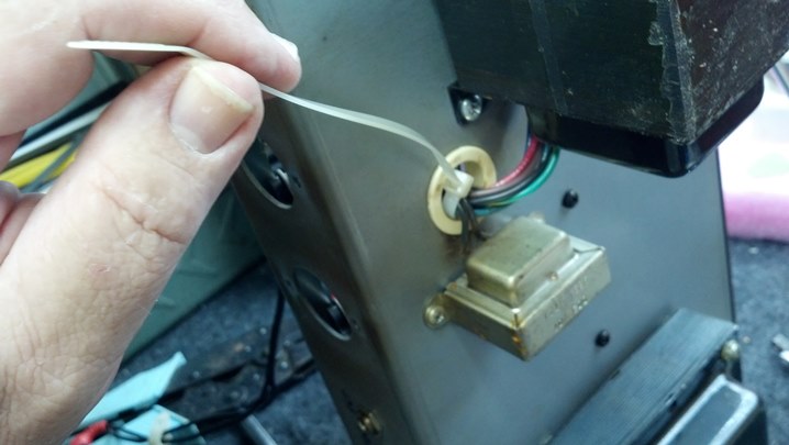
 All of the wires to the output transformer go through this TieWrap. We’ll snip this to get it out of the way for now.
 Here are the output transformer leads. Now, we unscrew the transformer from the chassis.
 I compared the two transformers. The bases are lined up, but the top is misaligned. What the…?
 Yes, the feet and bottom of the frame is aligned.
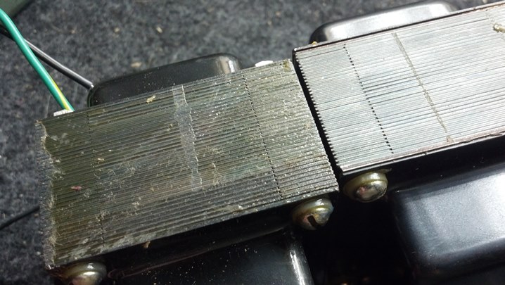 But the top of the lamination stack is definitely displaced on the top.
 Here, the laminations are parallel, but the straight edge shows that the old transformer is definitely parallelogrammed.
 A phone call to the owner reveals that this amp was in a serious car wreck about five years ago.
 That wreck explains why the bottom of this amp is filled with broken safety glass. The force of the car wreck deformed the output transformer. I’m guessing that as the deformed transformer heated up, the internal insulation broke down somewhere because the windings were stretched by the deformed transformer.
 Let’s bolt down the new transformer. Here, the leads are fished through the grommet in the chassis.
 A replacement TieWrap is installed in place of the old one. The small transformer is the power supply choke.
 More TieWraps are applied to dress the leads in a manner similar to the original.
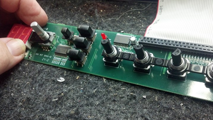
 I’m pretty confident that the unit will work fine now! Let’s put everything together, including all those knobs!
 Here are the new jacks.
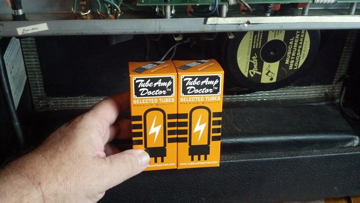 The new output transformer deserves a new set of tubes.
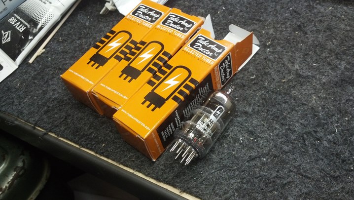 These preamp tubes were ordered at the same time.
 A one ohm resistor in series with the output plate circuit allows us to directly read the idle current of the output tubes. 60mV corresponds to 60mA of bias current, exactly what Fender specifies.
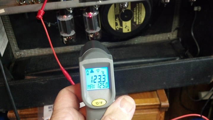 Another temperature check is performed after everything warms up.
 This little thermometer came from Harbor Freight. It works surprisingly well for a $20 infrared thermometer.
 We are restarting the four hour test from the start.
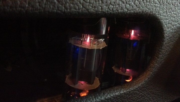 If you look closely, you can see a blue beam of electrons flying into the tube envelope through a small aperture in the plate. These bottles are happy!
 This road warrior has a new cover!
Listen to this amp in action at http://billybourbonmusic.com/ and support this artist!
Thanks for reading all the way to the end!
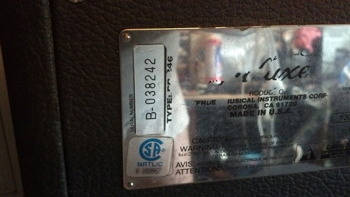
CONTACT – David Latchaw EE
281-636-8626

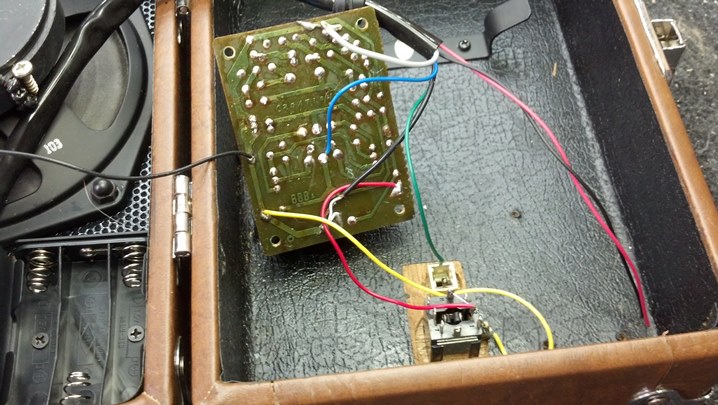
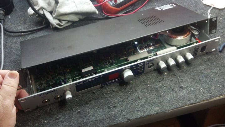
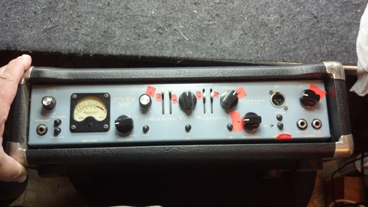 The owner said that he would clean up the front panel. Just get the thing working.
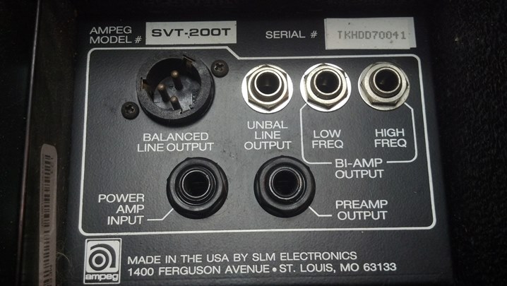
 The steel chassis was just the ticket to keep everything in its place. You can see the Trace Elliot heritage in this brand.
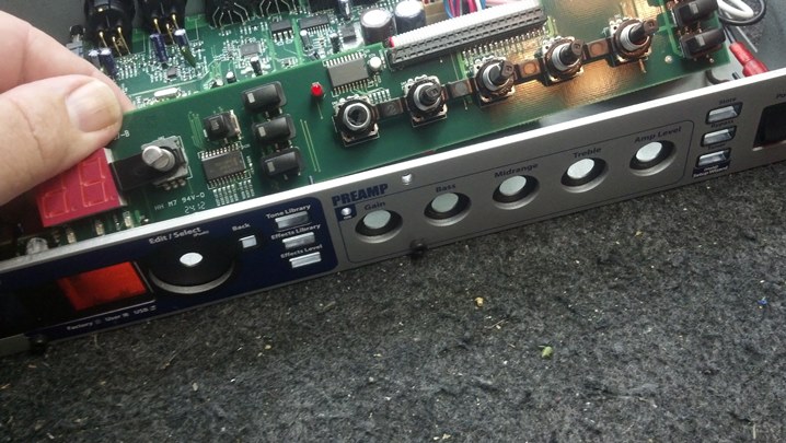
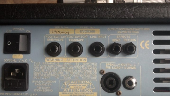 Here’s a close-up of the rear panel. The footswitch must have a pair of switches and a pair of quarter-inch plugs. The line input jack is an interesting feature.
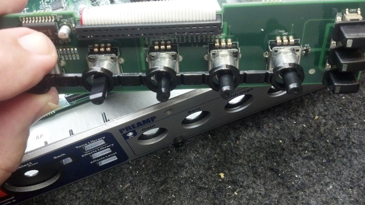
 These plastic caps covered the screws that secured the chassis to the case. Well, it appears someone has been here before us!
 A little care and a #3 Phillips was enough to bite into these screws and get the unit open.
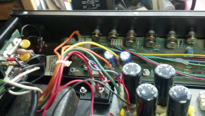
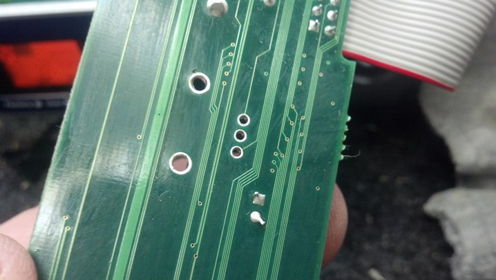
 Here, the power amp board is pulled free for inspection. That’s some big wire!
 Can you see the failed solder joint? The four elongated tabs are the terminals on a large full-wave bridge rectifier.
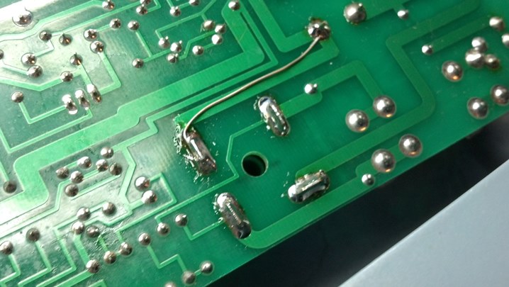 Each of the solder joints were de-soldered and then re-soldered with fresh solder. The joint that failed may have been on an ever-so-slightly thinner trace, so a jumper wire adds some circular mils of copper to that part of the circuit to keep the temperature rise of the circuit board down.
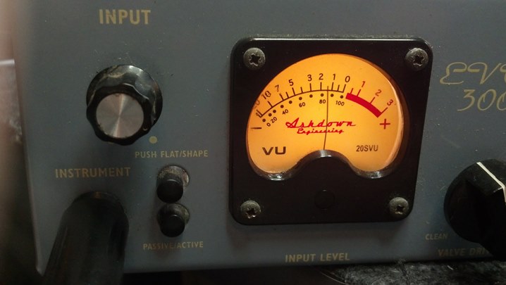 Behold! Everything comes alive! This meter is really a nice-looking feature.
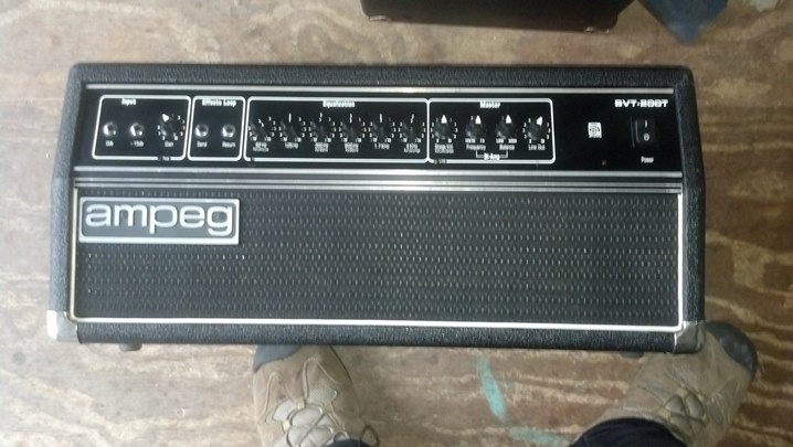
 This unit is conservatively rated at 300 watts. The unit barely got warm after four hours at that power level. I think we fixed it!