Wireless Shure SM58 Battery Leaked

This microphone was part of the estate of an amateur journalist. As she moved into treatment and into hospice, there were other concerns besides removing the batteries from unused equipment. Could the Unbrokenstring Crew revive this unit and make it usable again?

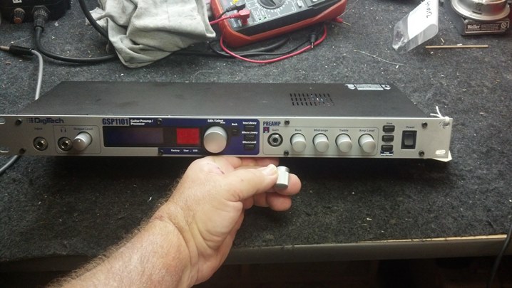
This microphone is a basic SM58 capsule coupled to a battery-operated VHF FM transmitter.

These are often seen in many performance venues as well as in worship, news-gathering, and business settings.


The 9v battery has leaked.  We will need to disassemble the unit to clean up the mess.


These VHF units are on frequency allocations that are shared with other services and may be subject to interference.  However, these units work well if you are fortunate enough to be in a part of the country where interference is low.


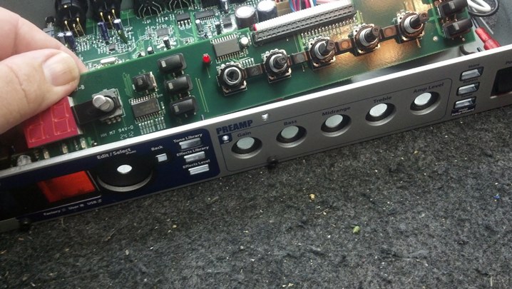
The microphone capsule is built into the head of the microphone, which unscrews from the electronics.  Connections between the capsule and the electronics are reliable regardless of how many turns are necessary to tighten the threaded bodies together.


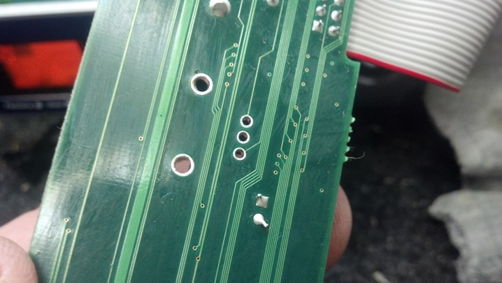
The gold fingers touch those rings seen in the previous picture.


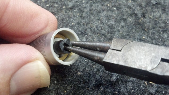
This inside snap ring keeps the electronics inside the housing.


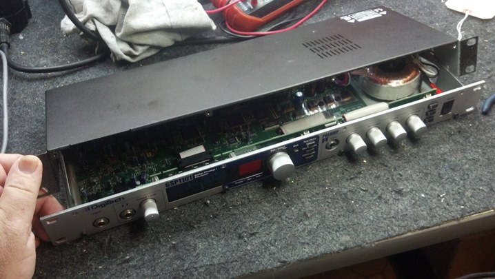
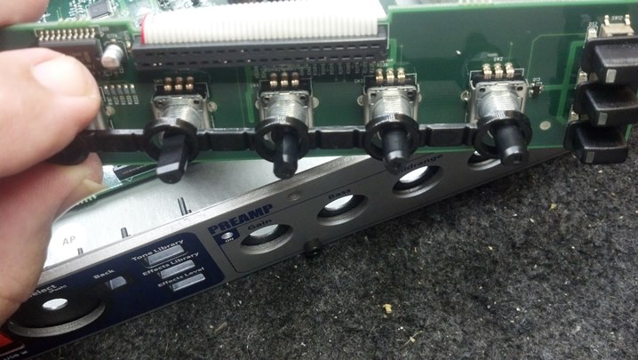
Before we remove the electronics,we need to get the switch actuators out of the case.  The cover removes easily enough.


The switch actuators come straight out.


This is looking good!


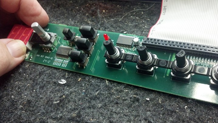
This is the complete analog FM transmitter.


Working with the battery contacts is much easier now that the case is out of the way.


Reassembly is the reverse of disassembly.  Wow, that’s profound…


These big tweezers are all I need to get the inside snap ring back in place.


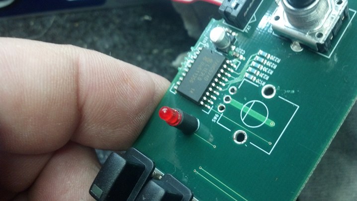
Reassembled, the new battery is installed and we have a green light!


The receiver indicates that an FM carrier is present.


We have an intermittent problem with audio out of the microphone.  We need to look at the capsule.


I guess we’ve screwed the pooch by now.


The wires are cracked where they emerge from the solder joints.  These will be reworked.


This brass adapter goes between the capsule and the rest of the housing.


We are back together again!

Thanks for reading all the way to the end!

CONTACT – David Latchaw EE
281-636-8626

Maxtone CB Wah Wah Pedal Repair

George had this wah pedal in his collection but realized one day that it didn’t work.  Could the Unbrokenstring Crew help?

These pedals are common but there is very little literature available on them.  That won’t stop us!


On the bottom of the unit, we find this text.


And, we find this text.  Not made in PRC (Peoples Republic of China!)


The power jack is the older mono 3.5mm jack often seen on period pieces such as this.


Peering between the pedal and the base, we see the rack and pinion that runs the potentiometer, and the bypass switch.


When we open the unit, we see that the potentiometer has come loose from its mounting fork.  The battery has not leaked.  In fact, it’s still reading nine volts!


You can see the fork where the potentiometer mounts.  All of the hardware is present and accounted-for.


We have re-mounted the control where it belongs.  This requires some adjustment, as we will see later.


From the outside, we can more clearly see the rack and pinion that drives the potentiometer.  Also, the bypass switch is really high.  This needs to be adjusted first so that it switches only when the pedal is all the way down.


Here we see the bypass switch is mounted much lower.  When the pedal is pressed downward, we hear a clean ‘click.’  This is an indication that it is adjusted correctly.


On the inside of the unit, the jam nut is tightened so that the switch stays in this position.


A little bit of petroleum jelly serves as a lubricant for the rack and pinion.  The screw to the right adjusts the mesh ‘pre-load,’ keeping the teeth aligned, yet minimizing the sideways load on the shaft bearing inside the potentiometer.  The gears are ‘slipped’ until the desired portion of the pot shaft rotation is in the correct place (relative to the pedal) to give us proper ‘wah’ action.


The actual ‘wah’ circuit is little more than a treble boost/cut circuit.   Now that everything is together, the unit is tested with a guitar and amplifier.  Now that we have confirmed that the portion of the pot rotation is OK for this unit, all the screws are tightened.


George said that he installed a new battery, so this one stays.


We are all back together and ready to return to the pedal board.

Thanks for reading all the way to the end!

CONTACT – David Latchaw EE
281-636-8626

Ibanez / Stratus TS-9 Clone Pedal Repair

What do we have here? This pedal is completely custom inside and out.  Who made it?  And why does it not work?  Can the Unbrokenstring Crew decipher this jewel and get it working again?
Matt received this as a gift after a live show, from an appreciative fan.  It has an honored place on his pedal board.


Google is of absolutely NO help deciphering any of this text.


Very nice circuit board!  This is a Tube Screamer circuit, with several types of LEDs and diodes selectable in the clipping circuit.  Nearly every aspect of the circuit topology is ‘bend-able’ in this pedal.  Very cool!


This unit uses a very nice, high-quality Burr Brown operational amplifier chip and precision components throughout.


Our principle problem is immediately apparent.  See the broken wire on the output jack?


We have another broken wire on the switch.  Solid (unstranded) wire is easy to work with, but is prone to cracking and breaking more quickly than stranded wire.  But solid wire is widely used in the pedal building world.


Stratus is a supplier of ‘build your own clone’ pedal kits.  Their catalog confirms that this is a Tube Screamer clone.  Oh, and we found more broken wires.


The common ground circuit at the output jack relies on the conductivity of the enclosure.  When the enclosure is painted, as this one is, one can have an intermittent electrical connection.  Here, I’ve removed the jack to scrape some paint and add a toothed lock washer for better connection to the pedal enclosure.


This tool is handy to keep jacks from turning while the nut is tightened.  These are designed for hollow-body guitars, but work almost anywhere a quarter-inch jack is found…  for instance, here.


I wonder whose cat this is?

Thanks for reading all the way to the end!

CONTACT – David Latchaw EE
281-636-8626

Sovtek Small Stone Pedal Refurb and Update

The modulation rate control on this wonderful Sovtek Small Stone phaser effect pedal had broken. While the unit is in the shop, could the Unbrokenstring Crew also add a 21st century DC pedal power jack to the unit?

Like a message in a bottle, this pedal has the look and feel of a relic from another planet. Even the switch looks like alien technology.

Removing the top cover reveals a heavy steel plate that holds the major components.  Look at the LED holder!

The control for the phase modulation had disintegrated.  Not much was left holding the shaft in place.

The back side of the modulation control was not out of the ordinary beyond the Cyrillic alphabet. Perhaps it could be rebuilt using parts from another similarly-sized potentiometer.

We have removed the old potentiometer from the circuit.

The tabs on the back cover of the potentiometer can be peeled back in order to disassemble the unit.

Interestingly, the internals of this control are completely different than what we might expect from a domestic control.  This potentiometer is a ‘reverse audio taper’ component.  The Russians achieved this by mounting the resistive element on the opposite side of the main wafer of the control, effectively reversing the direction of the taper.

So, it appears that we need to find a control that is close to the physical size of the old part, so we can reuse the knob.

We are working in millimeters here, in case you are wondering.

An aluminum bushing allows this smaller shaft to fit in the Russian knob.  Perhaps we have another degree of freedom in our search for a proper replacement.

This bushing can be removed…  a good thing that will allow us to do some gun-smithing if we need to do so.

The knob is not quite big enough to allow a quarter-inch shaft to be substituted.

So, we located a reverse audio taper control custom-designed for Neve recording consoles.  Yeah, I got connections.

This part has an appropriately-sized shaft that will permit us to use the original knob.  Good news!

The new control is wired into the circuit in the same manner as the old one.  Teflon spaghetti tubing handles the high-temperature insulation duties here.

These little spacers were rattling around in the enclosure after the circuit board was removed.  Where do these go?

Turns out, they are spacers that go on top of the cast bosses in the bottom of the original box.

The new power jack is mounted and wired into place, along with new steel Switchcraft in and out jacks.

The whole arrangement is now fitted back into the case.

An internal nine volt battery is used for powering this unit for checkout.

We have a winner!  Time to tighten down the screws and button this unit back up.

Here is the top cover with the new control installed.

The case cover is now back on.

The owner wanted to leave no question regarding whose pedal this was.  Mine!!!  Mine!!

Thanks for reading all the way to the end!

CONTACT – David Latchaw EE
281-636-8626


Digitech GSP1101 Effects Processor Repair

A frantic spouse called to explain that she was vacuuming and hit this ‘thing’ and broke this little piece off it.  Could I fix it before her husband found out?  The Unbrokenstring Crew to the rescue again!

01GSP brokenThe gain knob on this unit is a rotary encoder.  This component is available from several vendors.

02GSP what to doShe kept the knob, which is GREAT news, because although the rotary encoder is available, the knob is not.

03GSP salvage knobThe remains of the shaft of the rotary encoder was removed from the knob.  So far, so good.

04GSP opensesameLet’s get to work replacing the broken rotary encoder.

05GSP knobs offAs is the usual case, all the knobs come off first.

06GSP board looseThe circuit board lifts away easily.

07GSP spacer1These cool little plastic spacers set the geometry of the rest of the buttons and controls.

08GSP spacer2We will put this piece away somewhere safe while work elsewhere continues.

09GSP remove oldTo minimize the stress on the circuit board while removing the old component, the body of the broken rotary encoder is cut away from the component leads at an angle perpendicular to the circuit board.

10GSP part goneWith the component cut away from the circuit board, de-soldering the legs becomes trivial.

11GSP clear backThe component legs are gone.  This is a high-quality circuit board, double-sided copper and plated-thru holes.

12GSP clear frontBoth sides of the circuit board are cleaned up.

13GSP new partHere is the new part, ready to be soldered onto the circuit board.

14GSP reassemble1We are ready for reassembly.  That plastic spacer is re-installed as it was before.

15GSP reassemble2The cable carries all the signals back and forth to the front panel.  I like this bit of orgami.

16GSP reassemble3The circuit board is held in place by the bodies of the controls, which are in turn bolted to the front panel.

17GSP knobs onEverything is back together, ready for testing.

18GSP power onThis looks good!  While we were at it, we will do a factory reset.

19GSP final testNow, everything is as it once was.  And the husband was scolded for leaving his toys on the floor, where she could hit them with the vacuum.  Maybe I could sell him a rack case?

Thanks for reading all the way through!

CONTACT – David Latchaw EE
281-636-8626