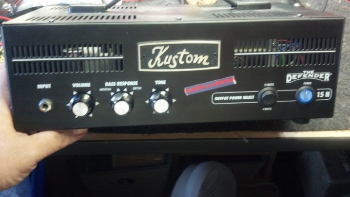
Mark’s future SIL picked up this little guy from the ‘friend’ he loaned it to, but it was mute when he got it back. Could the Unbrokenstring Crew make it audible again?
This unit is a very simple guitar amplifier, with two power settings.
The rear panel has some good functionality, including a DI out and a loudspeaker impedance selector.
And, of course, we have the Name, Rank, and Serial number, plus a couple of QC stamps!
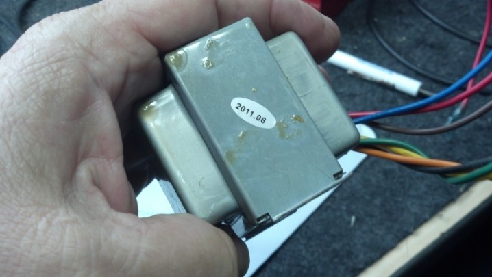
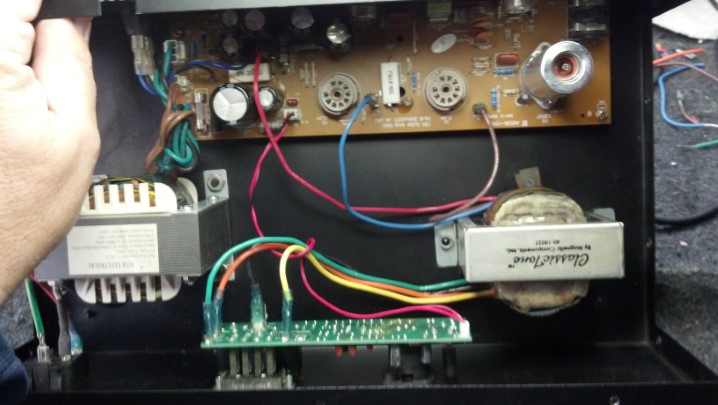
The output transformer is on the left and the power transformer is on the right. The input or high voltage side of the output transformer is shorted, reading about 6 ohms. This should be about 10,000 ohms.
The date code on the output transformer says that this part is not old enough to fail. I speculate that it was made China-Cheap.
These specs are really useful, because the new output transformer can be sourced so that these ratings and connections can be matched.
And here is our new part. It is a little bigger, so it will be mounted at a right angle to where the old transformer was mounted.
The new transformer is bolted in. The wire color on the new transformer matches the wire color on the old one. This is too easy!
A drop of LokTite thread locker is added to the bolts to keep everything where it belongs.
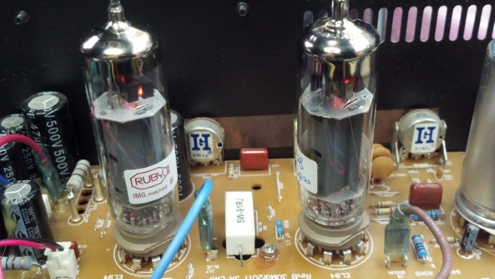
New tubes are necessary as the old ones had cooked and were not anywhere near matched. This amp uses a novel circuit to split the phase of the audio signal driving the power tubes, so these tubes need to be matched.
The amp is working and has passed all the final tests! And it doesn’t sound bad!
The four hour burn-in starts after the top cover is installed. For a simple amplifier circuit, it does a good job of fighting against the silence.
This wonderful old Marshall JCM900 lives in a recording studio. It was due for a set of tubes and a million-mile checkup. Could the Unbrokenstring Crew refresh this head and resolve the tiny issues that had arisen over the years?
In simple terms, this head has two channels that share a common tone stack, effects loop, and reverb tank. The amount of reverb, as well as the gain and volume, are independently adjustable.
Name, rank, and serial number, please.
The effects loop is accessible from the back. This unit is recording-friendly, with outputs for ‘wet’ and ‘dry’ signals.
The Business End. This amp can be switched to 50 or 100 watt output power.
Two fuses are used in the high voltage plate supply for this amp, which is a nice touch and will add something to the story later. IEC mains power socket and a line fuse rounds out the rear panel.
These power tubes have pushed billions and billions of electrons around, and some of those electrons have interacted with the inert gas inside the glass envelope. Do you see the frowning face in the upper insulator? The brown scorch mark is his beard.
These great tubes have delivered a long service life and are now just about worn out.
Interestingly, Marshall delivered these heads with 5881 tubes, a military 6L6. Later 6L6GCs dissipate more power and take higher voltages. You can read Internet posts regarding the battles between Marshall in England and American importers; the latter changed the tubes on new amps to 6L6GCs because they believed the 5881s would not last through the warranty period.
And here we have the reverb tank.
A walk through the bottom of the unit shows us the output transformer. The red and black leads to to the reverb tank.
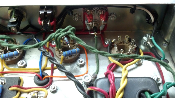
On the left is the preamp circuit board containing the input jack, tone controls, and signal switching. The tube sockets are discretely wired, and on the right is another circuit board handling the effects loop jacks.
More views of the preamp board on the left and the output jacks on the right. Tube sockets are in the middle.
At the lower right side of the output circuit board is the power supply power resistors, rectifiers, and fuses
The large blue items are the filter capacitors. These are in excellent condition and will not be replaced today.
The power transformer and power switches are mounted directly to the chassis.
This blue control sets the idling current (bias) for all four tubes. The current splits thru R28 and R29 to manage a pair of tubes each, part of the 50W/100W power control circuit.
The Unbrokenstring Crew are big fans of DeoxIt products. Here, we have sprayed a little D100 into the cap, and then soaked a pipe cleaner in the solution.
The pipe cleaner works well to clean and recondition each individual octal tube socket contact.
We will also wipe off the pins on the bottom of each tube.
So with the tubes installed and operating into an 8 ohm resistive load, we set the idle current for one pair of tubes. But the two sides don’t match.
Here, I’m using my good Fluke bench meter to confirm that one pair of tubes is idling at 50 milliamps, while the other pair is idling at about 41 milliamps or so. Both meters are in good agreement with the values measured, but I’ll stay with my good Fluke to investigate the situation.
Plate current causes heat to be dissipated in each tube. The V1 and V4 tubes are about 114 degrees C. while idling at about 41 milliamps.
The V2 and V3 pair are a little warmer. These tubes are idling at 50 milliamps. The temperature difference confirms the validity of the different idling currents… but why are they different? They share one transformer winding. We paid big money for matched tubes (which, when swapped around, make no difference…) More work!
Remember seeing separate fuses for plate current on the back of the amplifier? Checking voltage drops in the entire plate circuit, we see that this fuse drops about 0.2 volts across it more than the other fuse. Does that tiny voltage drop make any difference?
The fuse for the V1/V4 pair of tubes measures over half an ohm (meter zeroed for test lead resistance.)
This is the other fuse, for the V2/V3 pair plate circuit.
This fuse measures a tiny bit smaller resistance from end to end. Does this actually account for the higher current?
Sure enough, those voltage drops and differences in resistance accounts for about 10mA difference in plate current. New Fuses, Please!
While we’re at it, we will clean the fuse caps with DeoxIt, just as we did with the tube pins.
And the fuse holders will be similarly cleaned. (Hint – these pipe cleaners are perfect for cleaning other hardware besides your tobacco pipe.)
This line filter capacitor is scorched by a power resistor that was pushed up against it, perhaps a result of rough handling during shipping.
Components that are used on AC power require all sorts of safety certifications, which this part has.
I could probably leave this part in the amplifier, but film capacitors are cheap and if this were my amplifier, I would want it taken care of in a proper manner.
So here is the new line capacitor. The power resistor will be moved away from this guy when it is installed.
The filter capacitors in the bias circuit were also replaced, while troubleshooting the plate current imbalance.
Of course, replacing those parts requires access to the bottom of the circuit board.
While we have the circuit board up and out of the way, we can catch a glimpse of the discrete-wired tube sockets. This is a much better way to wire vacuum tube sockets, rather than solder them to a printed circuit board IMHO, because the tube sockets expand and contract much more than the circuit board material, whereas the discrete wire can just flex with the expansion and contraction.
This little bit of trimmed wire was stuck on the bottom of the circuit board. This will be no issue unless it comes loose, which it might do just as you are ready to go on stage and start the set.
Now this amp is running like a clock. The waveform represents the voltage across eight ohms driven with 110 watts, with a 440Hz sine wave injected into the input jack.
The chassis goes back into the case. I removed the power tubes for this step because I didn’t want to risk breaking anything in case I got stupid. The red and black cables to to the reverb tank.
Everything is checking out!
The sheet metal rear panel is much easier to align when the unit is face-down on the bench.
Zenith televisions were advertised with the slogan “The quality goes in before the name goes on!” After a four hour burn-in, the sticker is affixed on the output transformer side of the rear panel.
Partially submerged in the flood waters of Hurricane Harvey, this combo amp was rescued when the waters receded. Could the Unbrokenstring Crew turn this insurance claim into a working unit again?
At first glance, this unit is in pretty good shape. Fortunately, the flood waters around this unit were not salty, but fresh rain water. The grille cloth was not badly stained, and much of the exterior grime was superficial.
Not much damage had occurred to the cabinet; some warpage was beginning to appear in the bottom baffle. The interior was still wet. This implied that, if the drying-out process could be controlled, no further damage to the cabinet would be sustained.
Can you see some rust on the screws?
This side has some mold.
The bottom Tolex has some mildew beginning to form. Look at the rust beginning to form on hardware in the foreground.
The handle was beginning to rust. This could be managed.
The handle and the Tolex is cleaned and reconditioned with this, which also gives us a clean lemon scent!
This is the top of the reverb tank. Yes, beads of water, still on the exterior of the tank.
The previous owner had padded the top of the tank with gray foam, and the bottom with cardboard. The cardboard was soaking wet.
Reverb tanks are inexpensive, so we will just order a new one.
The paper cone of the loudspeaker was intact. This loudspeaker will be replaced by the new owner.
Moisture inside the amp chassis has swelled the turret board.
Water has reacted with the solder flux, creating a brown crust around all the solder joints. The components still look pretty good, although they cannot be trusted now.
Corrosion on the tube socket contacts testifies to the presence of liquid water here. Note also that the zinc plating on the once-shiny chassis is turning cloudy. This tells us that the zinc is doing its job as a corrosion-inhibiting plating, sacrificing itself to protect the steel underneath.
The cabinet hardware is washed in Rust Biox to clear away the rust. This chemical is available in Europe, but of course, The Unbrokenstring Crew is just cool enough to have this material here in the U.S.
The nickel plating has very little iron to rust; This deposit is probably mud.
All the hardware is cleaned up. The Tolex is cleaned and conditioned with the furniture polish. The cabinet looks good as new!
A new tube chart is pasted inside the cabinet where the original one was located.
For the electronics, a hand-wired chassis from the estate of Darrell Shifflett of Texas Amplification is pressed into service. The Unbrokenstring was truly fortunate to buy the remaining inventory of Texas Amplification. This chassis was part of the inventory. Look at those shiny new jacks!
The knobs are, of course correct. This is a clone of a Fender Blackface Princeton Reverb, not built in California but rather in Houston, Texas.
Darrell was a master of the details. Even the front panel is Correct for this unit.
As a testament to Darrell, let’s just take a look at his workmanship.
The wiring and component placement is meticulous.
If original components were available, such as the carbon composition resistors, he used them. Modern flame-proof components are used where an improvement in reliability and safety without sacrificing sonic performance justified the upgrade.
Even the wire is period-correct, fabric-covered was used for the point-to-point wiring, just like the originals.
A bias check for EACH output tube is added to the rear panel. Millivolts measured from red to black correspond to milliamps of plate current.
The jacks and controls are name-brand and not the cheap stuff.
But just look at that fresh brass sheet used for the ground plane under the controls. The original brass probably didn’t look this good in Fender units when they were new!
The underside of this amp is just a voyage on the Good Ship Eye Candy!
The electronic tremolo circuit is duplicated on this turret board. Not sure why this turret board is warped, but it is electrically 100%.
Speaking of turret boards, just look at the meticulous care used to mount each component and route the leads. Even the bias potentiometer is nicely placed.
Comparing this layout against the original Fender drawings is just breath-taking.
I’m really jazzed about how the fabric-covered wire is carefully routed around the tube sockets.
We needed a new rectifier tube for this amp.
Darrell used Mercury Magnetics for all the transformers on this chassis… the best you can get!
With the power on, all the voltages are correct.
The new reverb tank arrived today.
The bag protecting the reverb tank is dry and ready to be used again.
These straps hold the reverb tank bag in place in the bottom of the amplifier.
The ON/OFF switch works as it should. Since the AC cord is a modern three-wire unit, the original ‘GROUND’ switch is wired as a STANDBY/ON switch.
This unit is ready to go back to the new owner, who will install the new loudspeaker. Pretty nice unit for having been under water!
The Unbrokenstring Crew knew that it would only be a matter of time before gear submerged in Hurricane Harvey’s floods came onto the secondary market, be it CraigsList, OfferUp, or even as used gear at a national retail music chain that I will not name here, but go by the initials “Guitar Center.”.
Who could turn down this awesome piece of gear at a great used-equipment price? But this guy blow fuses.
Carvin is an excellent brand. Their musical instruments are expertly crafted, and the electronics are top drawer. And this amp head has three channels!
The rear panel of this unit shows all the versatility you could possible ask for in a tube head.
The select-able tetrode/pentode bias switch and a ‘cabinet-voiced’ line out signal jack are cool touches.
Serial number, for those who are curious.
The tube chart is silk-screened right on the chassis.
But when we open the unit up and turn it over, we see rust. Some of the tan residue is rosin solder flux, which is OK. But at the very top of the picture is a black pit in the end of a socket pin, which has almost entirely rusted away and will require replacement. Most electrical component leads have a core of iron, which is then tin plated for solder-ability. If the tin is intact, water is not an issue. But how many component leads have literally rusted away? Has this unit been wet?
The reverb tank is functional, but shows signs of water exposure.
These springs are very hard steel, so they rust and deteriorate very quickly.
Confirming our wet theory, the Tolex on the bottom of the case is coming loose.
Did I remove those screws and not notice the rust?
Looking closely at the hold-down clips for the tubes, they are completely rusted.
The steel chassis is coated in white enamel, which is really Top Drawer. But receding flood waters left mud.
Tear-down is in order to assess the condition of the unit.
Everything has been wet.
This is the component side of the circuit board that holds the power tube sockets. All this crusty solder flux tells me that the rosin is ‘activated’ with phosphorus, a Good Thing to make good solder joints, but a Bad Thing if it gets wet.
The preamp tube sockets show the same reaction with the phosphorus. This will all need to be cleaned and reworked. Some of these leads are completely hollow as the iron core has rusted away. It will be better to replace the sockets.
Electrical problems around the circuit board caused the preamp tube on the left to overheat.
A complete overhaul and rebuild of this unit would be necessary to restore functionality and reliability. Most components should be replaced, including sockets and connectors. However, the customer purchased this amp because it was in his price range. The repair quotation was not in his price range.
If you are shopping for gear and see signs of water damage, such as loose Tolex, rusty hardware, or dried dirt where it shouldn’t be, you should consider having a tech go over the equipment to assess the condition and find potential reliability problems before you buy. Rusty transformer laminations are particularly troublesome, as the rust pierces the insulating coating between laminations and allows eddy currents to flow, potentially overheating the transformer. Transformers are expensive to replace.
This combo amp had lived a hard life and had finally quit. Grandpa wanted his grandson to get the amp fixed so that they could jam together again. Could The Unbrokenstring Crew bring this unit back to life? We begin with a quick tour of the rear panel. The ground switch is a tip of the hat to the Old Days of two wire AC.
The foot switch plugs in where the REMOTE SWITCH jack is coming loose. This gets fixed.
I’m surprised that this hadn’t ripped loose. The whole connector wil be replaced.
Name, Rank, and Serial Number, please!
What have we here? We found grandpa’s stash.
Let’s get this line cord wired correctly. Do you know what’s wrong?
The black wire goes under the brass screw. “Black on brass will save you ass.” You’re welcome.
The reverb tank connects to the main circuit board with this connector.
Even after all this time, the high voltage capacitors are still charged. Woah! This is my discharge wand at work.
Our first mystery… where does this nut go?
This is a fuse. No, you think that it is a piece of 16AWG wire, but it is a fuse. Or, it is where a fuse goes.
And here, someone was tired of the fuses falling out of the holders, or what was left of the holders.
The heat from the flow of current has wreaked havoc on this solder joint.
This probably smelled bad when it was hot.
Now that the introductions are out of the way, we need to start replacing this nonsense.
These are commercial fuse holders. These will replace all of the preceding nonsense.
The plan will be to install these new fuse holders at a spot in the circuit where they will be functional, yet out of the way.
The new fuse holders are held down with a screw. This hole is where the screw goes. Here goes!
Another hole is drilled for another fuse holder.
This hole is in the center of a trace. We won’t miss that copper. Much.
Insulating nylon nuts and bolts are used to keep the new fuse holders in place.
The traces in the burned circuit boards are replaced with this Teflon-covered wire.
Everything is now stuffed back into place. Not too shabby, if I do say myself.
Turning our attention to the rear panel, your sharp eyes may recognize this connector as a MIDI female panel connector.
To keep the connector hardware in one place, some of this Thread Locker is all we need.
We have the original foot switch. It needs a new cable, with a connector to match what we just installed in the amp.
This MIDI cable will be repurposed to replace the cable on the footswitch assembly.
We don’t need this connector. Instead, this end of the cable will be wired to the switches themselves.
The new cable is soldered directly to the switches Note the strain relief installed to the right of the picture..
This pedal is ready for action once again!
The amp is reassembled and is ready to go!
The four hour burn-in test is underway. I think we have rescued another vintage Peavey amp!