In part two of this series, The Unbrokenstring Crew converted this instrument to a Tune-O-Matic bridge with a Bigsby tremolo. Now The Unbrokenstring Crew will add a cut-out switch to this instrument.
.
Matt has specified this exact spot where he wants the cut-out switch installed. The sharp point of an Exacto knife marks the exact center of the hole where the new switch will reside. Because that’s why they call it an Exacto knife.
.
We need to remove the pick guard, so off come the strings. Again.
.
This nylon washer is used in the Bigsby system to, among other things, set the working height of the lever. Keep track of this!
.
A pilot hole is bored where the Exacto knife made the mark seen earlier.
.
The copper foil around the new switch hole is cleaned. We are now ready to install the new switch.
.
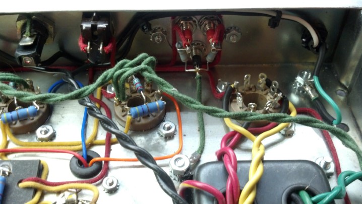
The resistor is installed across the contacts to limit the audible ‘pop’ that you sometimes hear when switching low-level circuits, like the circuits found in guitars.
.
Step Three is complete. This switch is not a push button, but is a spring-loaded momentary, center-off switch. Matt can quickly flick it from side to side for a very cool effect.
But wait! There’s more! In the last installment of this project, the cheap Chinese plastic nut has cracked. Tune in to see how The Unbrokenstring Crew upgrades the nut. Like A Boss.
In our first installment of this project, The Unbrokenstring Crew installed some new pickups in this cool offset-waist Jagmaster. Now, The Unbrokenstring Crew takes a deep breath. The inserts for the Tune-O-Matic will fall right at the edge of the body route for the Fender tremolo block. Extensive modification of the body is necessary for the next steps.
.
So The Unbrokenstring Crew takes an inspiration break. The first Fender-style guitar we’d seen with a Tune-O-Matic bridge was Larry Carlton’s Valley Arts ‘Strat’ copy, seen at about 9:10 in this video from 2012. WARNING: lots of funny Guitar Face to be seen throughout the video.
.
To position the TOM (Tune-O-Matic) bridge, we need to verify the dimensions of the guitar.
.
The twelfth fret is just to the right of the fret board marker. If you double that measurement, you get the ‘scale length’ of the guitar.
.
This metal machinist scale is eighteen inches long, so to complete the measurement to the bridge, we moved the end of the scale to the twelfth fret.
.
You will see that the existing bridge saddle blocks fall around the same place on the machinist scale. This looks good so far.
.
It’s time to get serious. The patient is prepped for major surgery. The black wire seen in the picture is the spring claw ground and the ground wire for the pickups.
.
The claw is coming loose and the springs will be removed.
.
After the new bridge and tremolo are installed, we won’t be needing this claw anymore.
.
With the spring tension gone, the original bridge just falls out. These inserts, though, should be tight, and they are not.
.
Both of the inserts had broken out. This points to the main concern with this modification e.g. how to install new inserts for the TOM bridge, in the right place, with enough wood around them to assure mechanical stability and sustain. This was a significant question in the planning stages of this project.
.
With the pick guard assembly temporarily in place, we can begin to establish the geometry of the new parts.
.
The outline of the pick guard is lightly traced on the surface finish of the instrument. The starting (and ending) finish is matte black. This gives us considerable flexibility when doing the modifications and refinishing the instrument when modifications are finished.
.
Some tape holds the machinist scale in place, leaving our hands free to do some marking down on the body.
.
The TOM bridge will go about here. Guitar Cognoscenti advised that the TOM bridge should go about 8/64ths of an inch beyond the 1x Scale Length for the instrument, because of the increased string length which occurs when the string is deflected when fretted, and other effects. Thus, the mark for the center line of the TOM bridge is at the 12 and 56/64ths point under the machinist scale.
.
The measurement made in the previous picture is expanded across the battle space so that the TOM inserts can be properly placed. Do you see the issue with the new TOM bridge placement?
.
While we have the 24 inch artist’s scale out, let’s check to see what sort of clearance we have under the plane of the fret board to verify that the TOM bridge will fit. If it doesn’t fit, we can shim the neck up a bit and create more clearance.
.
The exposed end of the ruler gives us an idea of where we are on bridge and neck geometry. This number goes into the notebook for later. Oh, and we have both English and metric systems well-represented here.
.
Let’s move to the other axis, and establish the actual center line of the guitar. A string is fastened at the nut between the D and G slots.
.
The position of the neck is the determining factor of where the bridge shall be, not necessarily the guitar body; There will be room for adjustment later if we need it, but let’s get it right while we’re here.
.
The center of the bridge is marked on the tape.
.
Before we go any farther, the original bridge is placed back on the body as a sanity check for the work done so far. As if sanity had any meaning at this point…
.
Another number to go into the notebook is the original string width at the bridge. As we planned, the TOM bridge string spacing is really close to this measurement.
.
The breakout from the original bridge inserts need to be addressed, because we really want as much solid material in this area as we can get.
.
Both inserts broke the body out. Some instruments are best repaired by just router-ing out the entire top and substituting a slab of maple. However, with the routes on the back side, nothing would be left of this guitar body.
.
These chips will be glued back where they belong, using hide glue. We avoided using a water-based adhesive such as Tite-Bond because the wood would swell from the water, then gradually shrink again over the next few months, rendering our efforts to fill all the cavities moot.
.
This damage is repaired well enough to support the steps to follow.
.
Birch is the less-beautiful cousin of maple. It has very little figure, and is very straight-grained. These birch dowels are perfect for filling the original holes where the inserts were installed.
.
After adding some protective tape, the dowels are cut flush with this Japanese saw.
.
I like this saw. So you are going to see lots of pictures of it today.
.
I think you get the idea now. Yes, I like this saw!
.
The blue strip that you see is the edge of the blue masking tape seen above. Note how close the edge of the routes are to the center line of the new bridge. All this needs to be filled-in so that the new inserts can be secure.
.
We will work on this side for awhile. The neck is off and is out of the way.
.
Much of the paint in the interior of this body is conductive shielding paint. Paint is not a good surface to glue anything to, so the Dremel tool and a sanding drum removes it all. This body is actually some very nice wood!
.
Paint is removed all the way around the tremolo block route. No electronics will go down here, so I’m not worried about shielding.
.
The tiny lip remains at the bottom of this route. This lip is actually on the front face of the body of the guitar. The Unbrokenstring Crew will leave it in place as a depth guide when installing the filler blocks.
.
Since the neck was off, we took a moment to clean up the bottom of the neck pocket. A clean, hard neck pocket is essential for good guitar tone and sustain, as it forms the counter-spring for the strings themselves.
.
Only the bottom was scraped, and then only enough to remove any soft, crumbly finish. The sides remain unmolested as they establish the geometry of the guitar, which we documented earlier.
.
Two blocks will be fabricated to fill the trem block route. The paper patterns are on the left, and the block of spruce plywood is marked with the approximate shape to fit the route.
.
These blocks are fitted to the original trem block route.
.
The faces are cleaned up just enough to allow the glue to do its job when these are installed.
.
These will stack into the body route. Do you see the little strip of glitter to the left of the spring route? That’s the original color of this guitar. Can you say “Glam”?
.
We were able to source this NOS bridge from a company that purchases broken guitars from Big Box Retailers and separates the brand new parts from the firewood.
.
This is the first meeting between the new bridge and the guitar body.
.
This brad-point wood bit makes a good center-finder. This bit is exactly the same diameter as the inside diameter of the stud hole in the new bridge. Everything is arranged so that the point falls on the center line drawn on the blue tape.
.
A shallow marking hole is then drilled to mark the spot.
.
This picture clearly shows the issue with adding a TOM bridge to a Squire body. There is no substantial wood around the hole where the inserts will be installed. Yet, we press on!
.
One last trial fit is performed for these filler blocks.
.
These plugs are ready to go.
.
These are a good, tight fit into the original trem route. Can you see the glitter?
.
The top side should be flush. The lip inside the route was left behind to align the plugs already in the body. Another piece of birch will fill this shallow cavity.
.
This little bit of solid birch is fitted to the opening.
.
Hide glue is applied liberally and the stack of filler blocks are glued into place.
.
With the glue dry, we are ready to keep moving on this project.
.
The top is masked off again so that the top of this filler block can be completely level with the rest of the guitar.
.
A cabinet scraper brings the top of the filler block down to the level of the top of the guitar, or at least to the same level as the masking tape.
.
We cheated and used some wood filler to close up all the gaps. This will be finish sanded after one more coat of filler.
.
For additional internal strength and rigidity, another block is fabricated to fill a bit more of the spring body route. The same birch plywood is pressed into service.
.
The new filler block is a very tight fit. The paint around it will be sanded away so that the glue around the block can bond directly to the wood of the guitar body.
.
This new filler block is now glued into place. You can see a layer of hide glue on the filler blocks already in place in the trem block route.
.
The matte black finish was matched, leaving only the pilot holes for the new TOM inserts. All of the remaining body routes will be foiled and grounded at the output jack. We are covering some interesting shapes today!
.
The pickup cavities are done.
.
The control cavities are completed. The copper looks spectacular against the matte black of the body of the guitar. Here you can see how the matte black finish came out over the unfinished filler blocks installed previously.
.
While we’re at it, let’s do the underside of the pick guard. Note that the seams of the tape are tack soldered. The seams inside the body are also tack soldered, to form a continuous shield.
.
A small tab of foil extends from the body routes so that the foil under the pick guard can be bonded together using a pick guard screw for compression.
.
Next, the holes for the inserts will be bored using this brad-point bit.
.
The tape marks the correct depth. We don’t want to drill all the way through the guitar, do we?
.
I couldn’t help myself. I had to place the new bridge where it goes just to gratify my curiosity.
.
And while I’m gratifying myself, let’s check the position of the Bigsby.
.
As we begin slowly boring the holes for the inserts, we can clearly see the boundary where the body ends (on the left) and the filler blocks begin (on the right.) This is one spot where we need the most strength and rigidity for best tone (and to keep the guitar from falling apart under string pressure.)
.
This aircraft drill bit is boring a passage for the ground wire that will engage the bridge insert. To the left of the picture is another dowel rod.
.
That distant dowel is in a hole on which the Bigsby is mounted. Using the eighteen inch long aircraft drill, we need to slant drill our way through the guitar body and hit that hole. Somehow.
.
More blue tape indicates just how far I must drill through the body. If I don’t hit the dowel by the time the tape hits the copper, I missed.
.
Inhale. Exhale. I hit it! Some wire left over from the spring claw is pushed through the holes drilled in the previous pictures. Yes, that wire made a ninety degree turn inside the body of the guitar. Kind of a big deal.
.
Using the Exacto Knife, the insulation on the wire is nicked in the proper spot so that the insulation can be removed, allowing the wire to touch the bridge insert, thus grounding it.
.
The insulation is removed so that the wire can form a compression joint with one of the bridge inserts, thus grounding the bridge.
.
The big clamp can apply plenty of force to seat the bridge insert. The one on the far side has already been pressed into place.
.
The ground wire is now joined with the wire from the pick guard shield and soldered to the foil in the control route.
.
The free end of the ground wire is stripped and ready to be compressed against one of the Bigsby mounting screws.
.
When the Bigsby is installed, the screw that goes here will compress the ground wire and make the electrical connection, thus grounding the Bigsby tremolo and strings. No wiring will be visible from the outside of the guitar.
.
Here is the newly-installed bridge and trem. The pick guard is placed temporarily for this picture. This project is shaping up well!
.
The Correct pick guard screws are now in hand and will replace the larger screws originally used on this guitar. The holes are partially filled with birch dowels and cut flush.
.
The exact center of each pick guard screw hole is established with this pocket drill bit.
.
Once the center is established, the hole can be bored using the Correct bit.
.
This was a goof. The outside of one of the TOM bridge inserts interfered with this corner of the pick guard. The drum sander on the Dremel tool corrected the oversight.
.
Here, we are finishing up with the pocket drill. I use the electric screw driver as a drill because it is slow and easy to control.
.
This is a good shot that shows the modification of the pick guard to fit the TOM bridge insert.
.
To assure that the studs fit snugly in the inserts, some copper foil is used as a shim over the threads of each stud to make electrical contact and to help lock the stud in place after adjustments are made.
.
Copper foil is added or removed until the stud fits snugly regardless of how much of the stud is threaded into the insert.
.
Little bits of copper foil are all it takes to get these studs shimmed up where they belong!
.
It’s time to string it up!
.
It’s a lot easier to get the strings on a guitar with a Bigsby if the ends are pre-formed to wrap around the roller.
.
TOM bridges are versatile insofar as the saddles can be removed and turned around to extend their adjustability. Note: do not lose these little clips. Don’t ask me how I know this.
.
Once the clip is off, the adjustment screw can be unthreaded from the saddle.
.
The bevel on the top of the block can go either direction. We can use this to our advantage when setting intonation.
.
This saddle has been turned around.
.
The screw keeps the saddle in place.
.
And the little clip keeps the screw in place. Again, don’t lose these.
.
We took a detour to de-burr the hole in this tuning machine. This tuning machine was masquerading as a string cutter. The Unbrokenstring Crew will not tolerate broken strings!
.
Step Two is complete. This guitar is a lot of fun!
In the third installment of this saga, The Unbrokenstring Crew will install a cut-out switch in this instrument, which silences the guitar whenever the switch is activated. However, this switch is not just a normal push button. Tune In next week for Episode Three!
Matt has many dreams. One of them was to have an offset-waist guitar with a Tune-O-Matic bridge and a Bigsby. And while we’re at it, a fresh set of pickups. And then, of course, a kill switch, because, why not? And there is Even More after that! This sounds crazy enough for The Unbrokenstring Crew to immediately roll up our sleeves!
.
And, yes, Matt is a star!
.
.
We have some added confidence that we can go crazy with this project because this is not the most expensive guitar in the world. But, as we shall see, it is a surprisingly good base for the modifications in mind.
Starting with the pickups, these factory humbuckers will be changed out.
.
Each factory pickup measures almost the same resistance, but we labelled them separately for the benefit of future generations.
.
A pair of P-94s grace the pickguard.
.
The Gibson P-94s look dazzling on this guitar! Matt really hit a home run in the esthetics department. And they sound awesome, as we will later find out.
.
A quick test of the wiring is performed by gently tapping each pickup with something metallic while the little Orange amp turns my taps into sound.
.
While we’re here, the pickup selector switch is tightened with this serrated nut compression tool.
.
Step One is complete. This guitar looks pretty snazzy!
In the next installment of this saga, The Unbrokenstring Crew will take a deep dive into serious Bod Mod and install a Tume-O-Matic bridge and Bigsby tremolo on this instrument. Tune In next week for Episode Two!
Partially submerged in the flood waters of Hurricane Harvey, this combo amp was rescued when the waters receded. Could the Unbrokenstring Crew turn this insurance claim into a working unit again?
At first glance, this unit is in pretty good shape. Fortunately, the flood waters around this unit were not salty, but fresh rain water. The grille cloth was not badly stained, and much of the exterior grime was superficial.
Not much damage had occurred to the cabinet; some warpage was beginning to appear in the bottom baffle. The interior was still wet. This implied that, if the drying-out process could be controlled, no further damage to the cabinet would be sustained.
Can you see some rust on the screws?
This side has some mold.
The bottom Tolex has some mildew beginning to form. Look at the rust beginning to form on hardware in the foreground.
The handle was beginning to rust. This could be managed.
The handle and the Tolex is cleaned and reconditioned with this, which also gives us a clean lemon scent!
This is the top of the reverb tank. Yes, beads of water, still on the exterior of the tank.
The previous owner had padded the top of the tank with gray foam, and the bottom with cardboard. The cardboard was soaking wet.
Reverb tanks are inexpensive, so we will just order a new one.
The paper cone of the loudspeaker was intact. This loudspeaker will be replaced by the new owner.
Moisture inside the amp chassis has swelled the turret board.
Water has reacted with the solder flux, creating a brown crust around all the solder joints. The components still look pretty good, although they cannot be trusted now.
Corrosion on the tube socket contacts testifies to the presence of liquid water here. Note also that the zinc plating on the once-shiny chassis is turning cloudy. This tells us that the zinc is doing its job as a corrosion-inhibiting plating, sacrificing itself to protect the steel underneath.
The cabinet hardware is washed in Rust Biox to clear away the rust. This chemical is available in Europe, but of course, The Unbrokenstring Crew is just cool enough to have this material here in the U.S.
The nickel plating has very little iron to rust; This deposit is probably mud.
All the hardware is cleaned up. The Tolex is cleaned and conditioned with the furniture polish. The cabinet looks good as new!
A new tube chart is pasted inside the cabinet where the original one was located.
For the electronics, a hand-wired chassis from the estate of Darrell Shifflett of Texas Amplification is pressed into service. The Unbrokenstring was truly fortunate to buy the remaining inventory of Texas Amplification. This chassis was part of the inventory. Look at those shiny new jacks!
The knobs are, of course correct. This is a clone of a Fender Blackface Princeton Reverb, not built in California but rather in Houston, Texas.
Darrell was a master of the details. Even the front panel is Correct for this unit.
As a testament to Darrell, let’s just take a look at his workmanship.
The wiring and component placement is meticulous.
If original components were available, such as the carbon composition resistors, he used them. Modern flame-proof components are used where an improvement in reliability and safety without sacrificing sonic performance justified the upgrade.
Even the wire is period-correct, fabric-covered was used for the point-to-point wiring, just like the originals.
A bias check for EACH output tube is added to the rear panel. Millivolts measured from red to black correspond to milliamps of plate current.
The jacks and controls are name-brand and not the cheap stuff.
But just look at that fresh brass sheet used for the ground plane under the controls. The original brass probably didn’t look this good in Fender units when they were new!
The underside of this amp is just a voyage on the Good Ship Eye Candy!
The electronic tremolo circuit is duplicated on this turret board. Not sure why this turret board is warped, but it is electrically 100%.
Speaking of turret boards, just look at the meticulous care used to mount each component and route the leads. Even the bias potentiometer is nicely placed.
Comparing this layout against the original Fender drawings is just breath-taking.
I’m really jazzed about how the fabric-covered wire is carefully routed around the tube sockets.
We needed a new rectifier tube for this amp.
Darrell used Mercury Magnetics for all the transformers on this chassis… the best you can get!
With the power on, all the voltages are correct.
The new reverb tank arrived today.
The bag protecting the reverb tank is dry and ready to be used again.
These straps hold the reverb tank bag in place in the bottom of the amplifier.
The ON/OFF switch works as it should. Since the AC cord is a modern three-wire unit, the original ‘GROUND’ switch is wired as a STANDBY/ON switch.
This unit is ready to go back to the new owner, who will install the new loudspeaker. Pretty nice unit for having been under water!
Lisa’s marvelous Fender P-Bass needed attention. Some of the open notes were dead, and the electronics needed some attention. Could the Unbrokenstring Crew sort it all out? I just love the pale yellow finish. Except for a string, everything is here.
Yes, it really is Made In Japan. Back in the day, ‘made in Japan’ was another word for cheap imported junk. Nowadays, this is some of the better stuff, particularly in guitars.
Name, rank, and serial number, please!
An electrical test shows that we have no output.
A quick look under the hood does not reveal an immediate problem. Hmmm…
Oh, this is it. The ground point for the whole unit is this potentiometer body. However, the ground wire to the output lead does not connect to the potentiometer body anywhere.
With that fixed, the remaining ground wires are cleaned up a bit.
The bridge ground wire made an intermittent connection to the bridge. We need to remove the green corrosion.
OK, the electronics are now all up to snuff, and actually look pretty nice.
While we’re here, we’ll tighten the output jack and potentiometers a bit.
The knobs go on now.
Final test is performed with a signal generator and another bass pickup. The signal generator excites the windings in a bass pickup from an Aria Pro II bass, which will be featured in a future blog post. The test pickup is brought near the instrument’s pickups, and the magnetic field carrying a test tone is coupled into the instrument’s electronics.
The dead open notes are traced to a cracked nut. Here, we’re cutting the finish around the old nut so that it can be removed cleanly. The Exacto knife gets a new blade for this operation.
The old nut comes out in two pieces. The crack expanded until the nut broke in two. That’s why we’re replacing it.
Here is the new nut that the customer wanted installed. Good stuff!
Oops. Houston, we have a problem This new nut does not fit the neck.
The new nut is just a tiny bit smaller than what is required for this neck. What gives?
We can clearly see the difference in the sizes between the old nut and the new one. This neck is the width of a five string bass, but it was delivered as a four string bass from the factory. So, we will make a custom nut for this instrument.
A Tusq blank is radiused to match the radius of the fretboard. I’m using an Exacto knife as a scraper.
The Tusq blank is cut to rough length with a fine saw.
It doesn’t take long to slice through the Tusq material with this blade.
This is a saw blade set that I use for sawing fret slots and general fine work on wood.
The blank is now shaped on the disk sander. A piece of birch plywood serves as a raised table that can be placed very close to the abrasive surface of the disk, necessary when shaping small parts.
The blank is now pretty close to the rough shape we need.
The first trial fit shows that we haven’t cut it too small, yet.
This is a little better. The ends are flush and smooth with the edges of the fret board.
In AutoCAD, a drawing is created showing the cross sections of the four strings and the width of the fret board in actual size. The distance between the edge of the outside strings and the edge of fret board, established by factory specs, is drawn, and the position of the outside strings fixed. We then subtract the diameters of the four strings from the width remaining. This result represents the space between strings, which shall be three equal spaces. This establishes the center lines of the inner strings. The spaces between the strings are the same, not the center-to-center distance.
But, to cut the string slots, we need to know where the edge of the fret board is, and where the center lines of the strings fall. These solid lines represent that information.
The lines which represent the centers of each string are transferred to the nut.
A shallow file cut is made at each string center. Here, we are checking these cuts against the template.
These shallow cuts represent the eventual center of each string.
These cuts were made with a triangular mill file. Nothing special, but accurate enough.
Here, we’re polishing up the sides and faces of the nut, in preparation for gluing the new nut in place on the neck.
The nut depth is established by the fret height plus a constant which is established by Fender (and can be adjusted a bit by a good luthier, like me, for best play-ability.) This is the Secret Sauce of making an instrument a great instrument.
The slot depth is now established by this stack of feeler gauge shims. They are held in place with rubber bands wrapped around the back of the neck. I’ve taped off the head stock so that I don’t scratch it up with the end of a file.
When the file touches the stack of feeler gauges, continuity will be detected by this multimeter, and it will beep. This is another check of slot depth, besides my eyeballs.
Here, the slots are cut. With a little cleanup and polish, this will be a good nut!
The nut is all done and polished. Looks good!
The action on this instrument at the twelfth fret is pretty high…
We have a metal neck shim between the neck and body, made from a piece of the machinist’s feeler gauge of the proper thickness to reestablish proper neck geometry. The metal shim is the hardest practical material for this purpose, with an accurate thickness, and better mechanical stability and hardness for greatest vibration transfer between the neck and body than a guitar pick or a piece of business card. This results in the best tone. And a set of feeler gauges are less than five bucks.
A quick adjustment gives us just the right amount of neck relief. (Sharp-eyed readers will spot the fact that the strings are off in this picture. This is the only pic I took of the truss rod adjustment, setting the neck flat while the neck shim was being sized. Who cares if my pics are out of chronological order?)
To set intonation, we needed to work on the bridge. Here is the underside of the bridge, probably not seen for decades.
The intonation screws were dinged. Here, we are chasing the threads with a die to clean them up. Yes, they are English/Imperial threads, not metric.
The bridge is tightened down and ready to go!
The moment we’ve all been waiting for! Add strings, tune up, intonate, and play!