Ampeg BA115 Bass Amp Falling Apart (Literally)

Back in August of 2017, one of these combo bass amps came through the Unbrokenstring Shop with cracked solder joints, which were probably a result of brittle lead-free (RoHS) solder on the circuit board.  The owner of this Ampeg saw that post and called up the Unbrokenstring Crew to ask if this amp could be fixed as well.  Here we go!

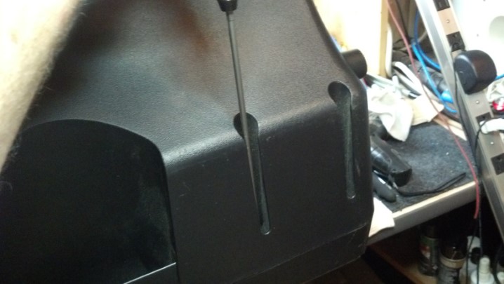
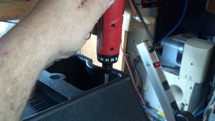
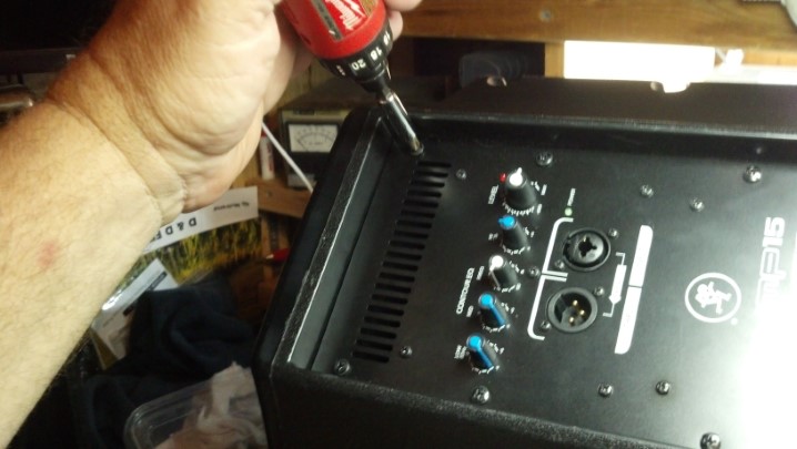
Disassembly and reassembly of the combo amp is exactly the same as was performed on the earlier post.  Here, we are starting this blog post with just the chassis on the bench.


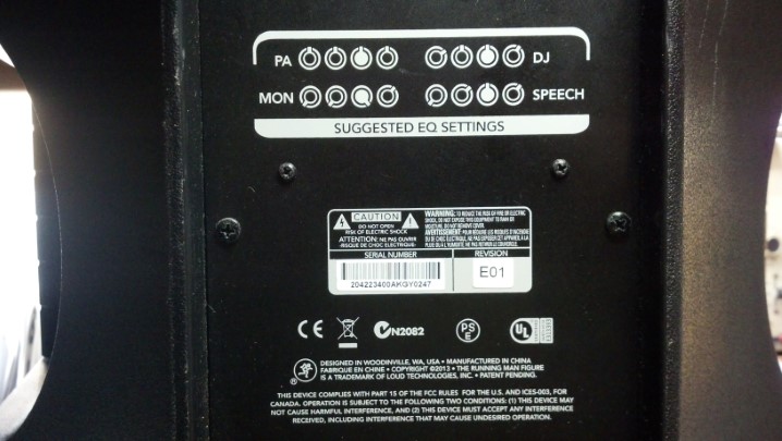
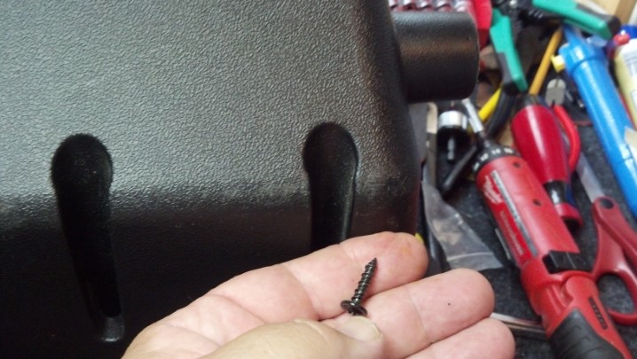
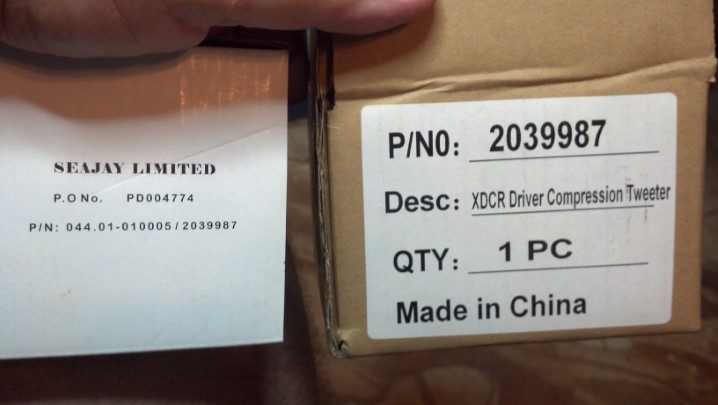
Name, Rank, and Serial Number, please!


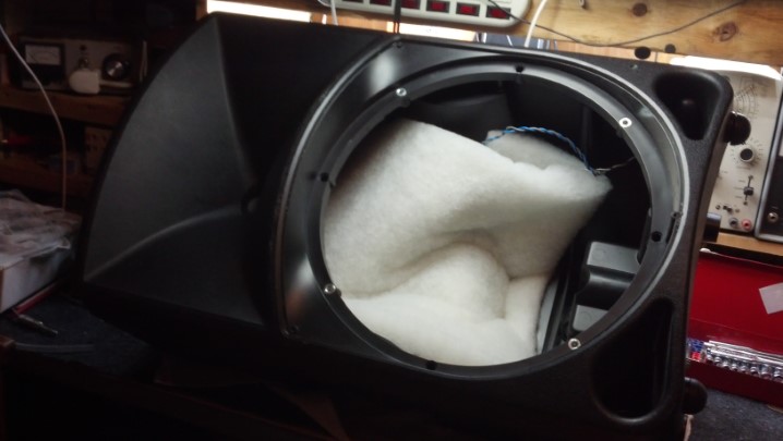
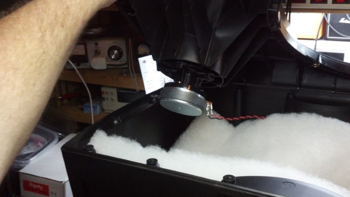
From above, everything appears to be as it should be.  No wires are hanging loose as was seen in the amp serviced in August, 2017.


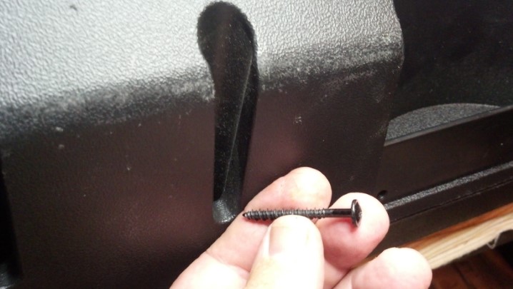
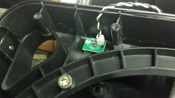
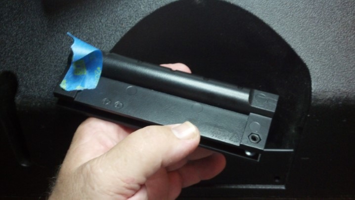
But once the circuit board was removed from the chassis, this rotary switch came loose from the circuit board!


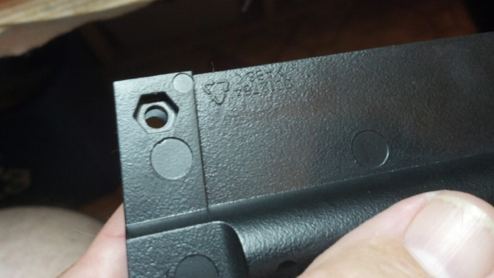
As was seen in the other repair, the metallurgy involved with the soldering process was to blame.  In addition, in my opinion, this switch was not the exact part that matches the footprint on the circuit board.  Note that the pins are bent inward to the center of the switch.


These pins are plated in gold.  This is a good thing for the component, but gold, in solution with molten solder (yes, the metals mix) makes the resulting solder joint brittle.  Here, some activated rosin flux is added to the gold plated pins to prepare them for a coat of tin-lead (non-RoHS) solder.


Tinning is complete.  In this picture, we can see the intentional bending of the legs to match the holes on the circuit board.


This is a high quality part, and works well in this application.  However, the manufacturing engineer at SLM was off his/her game that day.


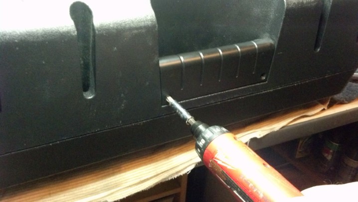
Our new solder joints will probably outlast the amplifier.


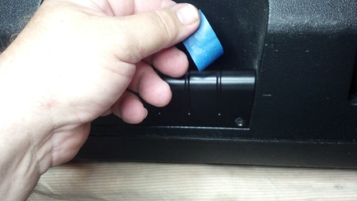
No parts were required for this repair, only labor.  This unit plays 100% now!

See the previous Ampeg 115 post for reassembly.

Thanks for reading all the way to the end!

CONTACT – David Latchaw EE
281-636-8626

Carvin MTS3200 Amp Head is the Victim of Hurricane Harvey

The Unbrokenstring Crew knew that it would only be a matter of time before gear submerged in Hurricane Harvey’s floods came onto the secondary market, be it CraigsList, OfferUp, or even as used gear at a national retail music chain that I will not name here, but go by the initials “Guitar Center.”.

Who could turn down this awesome piece of gear at a great used-equipment price?  But this guy blow fuses.


Carvin is an excellent brand.  Their musical instruments are expertly crafted, and the electronics are top drawer.  And this amp head has three channels!


The rear panel of this unit shows all the versatility you could possible ask for in a tube head.


The select-able tetrode/pentode bias switch and a ‘cabinet-voiced’ line out signal jack are cool touches.


Serial number, for those who are curious.


The tube chart is silk-screened right on the chassis.


But when we open the unit up and turn it over, we see rust.  Some of the tan residue is rosin solder flux, which is OK.  But at the very top of the picture is a black pit in the end of a socket pin, which has almost entirely rusted away and will require replacement.  Most electrical component leads have a core of iron, which is then tin plated for solder-ability.  If the tin is intact, water is not an issue.  But how many component leads have literally rusted away?  Has this unit been wet?


The reverb tank is functional, but shows signs of water exposure.


These springs are very hard steel, so they rust and deteriorate very quickly.


Confirming our wet theory, the Tolex on the bottom of the case is coming loose.


Did I remove those screws and not notice the rust?


Looking closely at the hold-down clips for the tubes, they are completely rusted.


The steel chassis is coated in white enamel, which is really Top Drawer.  But receding flood waters left mud.


Tear-down is in order to assess the condition of the unit.


Everything has been wet.


This is the component side of the circuit board that holds the power tube sockets.  All this crusty solder flux tells me that the rosin is ‘activated’ with phosphorus, a Good Thing to make good solder joints, but a Bad Thing if it gets wet.


The preamp tube sockets show the same reaction with the phosphorus.  This will all need to be cleaned and reworked.  Some of these leads are completely hollow as the iron core has rusted away.  It will be better to replace the sockets.


Electrical problems around the circuit board caused the preamp tube on the left to overheat.

A complete overhaul and rebuild of this unit would be necessary to restore functionality and reliability.  Most components should be replaced, including sockets and connectors.  However, the customer purchased this amp because it was in his price range.  The repair quotation was not in his price range.

If you are shopping for gear and see signs of water damage, such as loose Tolex, rusty hardware, or dried dirt where it shouldn’t be, you should consider having a tech go over the equipment to assess the condition and find potential reliability problems before you buy.  Rusty transformer laminations are particularly troublesome, as the rust pierces the insulating coating between laminations and allows eddy currents to flow, potentially overheating the transformer.  Transformers are expensive to replace.

Thanks for reading all the way to the end!

CONTACT – David Latchaw EE
281-636-8626

Epiphone PR-5E Acoustic Gets New Electronics

This wonderful instrument was rescued from an abandoned house.  It sounded good acoustically, so the new owner asked if the Unbrokenstring Crew could repair the electronics and get it playable again?  Let’s get to work!

This instrument is only a few years old, purchased and then cast aside.


An online source for specialty guitar parts had a 2018 model of the electronics.  Can we make it work?


The mounting scheme uses four screws in the corners.  Cleats will be added to the guitar so that the screws hold.


But the REAL advantage of the 2018 electronics is that the enclosure matches the curve of the body.


Common wood items such as yard sticks, tongue depressors, popsicle sticks, and paint stirrers are made from birch, the straight-grained ‘poor relation’ to maple.  So the paint department lady at Home Depot gave me this stirrer.


Cleats to tightly hold the electronics in the body are fabricated by hand.


Next, the cleats are sanded to fit the curve of the body on the inside of the bout.


These are ready to trial-fit.  The bevel on the corner, lower-left side, clears an internal brace in the guitar.


One shim goes here.  Note the angled pieces, which will catch the screws in the electronics.


To protect the finish, low tack painter’s tape is used all around.


These clamps will hold the cleats in place as the hide glue sets up.


Both cleats are installed and the hide glue is curing.


Additional reinforcement is added in the corners to give the screws more material to grip.  These bits will be in compression, so they don’t need to be super-strong, only tough.


Before we get too far, we need to do another trial fit.


I think we’re going to be good here!


I will pre-drill the holes where the screws will be installed.  This should minimize splitting of the small cleats.


The actual drilling will be finger-powered, using this pin vise.


All four holes are pre-drilled.


Yes, I know.  This isn’t terribly interesting.


The screws are installed.  Not bad!


The jack plate holds the battery and has both 1/4th inch phone plug and balanced XLR connections.  It was temporarily removed to give more access to the interior of the instrument.  The new electronics hook right up to the jack plate.


This is a new one on me.  This battery was in the guitar when it came in.  The Golden Thumbs-Up Emoji Award!


And, while we’re here, we’ll clean the instrument, string it, and do a setup.


The electronics come alive!


This is a cool tuner.  The LCD screen has a pointer that swings across its face.


Beauty is skin-deep, but what really counts is just below the surface.  This rescued guitar is ready to make music!

Thanks for reading all the way to the end!

CONTACT – David Latchaw EE
281-636-8626

TC Helicon VoiceLive3 Pedal Refurbishment

A lot of capable technology lives in this device.  However, if the musician can’t select a configuration because the big rotary selector knob broke off, then it’s e-waste.  Can the Unbrokenstring Crew bring this pedal back from the dumpster?

Pedals live on the floor, and there is plenty of dust to attest to to the fact that this unit has been working hard exactly where it was born to be.  No harm in cleaning and detailing this unit before we’re through!


The main issue here is the broken rotary encoder.  We have the knob, but not the shaft.


Time for a quick tour before we begin.  This pedal serves both vocal and instrument duties.  Flexible monitoring options are available, as well as 3.5mm stereo headphones out and line-in capability.


Separate paths are maintained through the unit for vocal and instrument signals.  Stereo effects are available.


Midi, USB in and out, and a power switch complete the rear panel.  That black rectangle above the USB ports is a cleat to tie off the power cord, to make it a little more difficult to pull the barrel plug out of the power jack.


It takes a lot to get into this box.  Let’s start at the bottom.


The bottom lid is off.  So far, so good.


The footswitches are VERY old school, rugged American made switches, proven reliable since the middle of the century.


Let’s remove the sides next.  This bracket on the side panel supports the bottom circuit board.


These are the external screws on the sides.


These are Torx-head cap screws, giving the device a cachet of ‘tamper-proof-ness’ unless you have the right tools.


Next, the rear panel comes off.  More Torx screws.


Under the side plates, metal plates support the unit to make a very strong metal box surrounding everything.


At last, we can get to the next layer.  The unit is still upside down.


I’m documenting where cables go.  This is a front-panel indicator assembly.


More cable documentation.  See the Ruffles potato chip?


Most of these cables will be marked with a Magic Marker to identify them for reassembly.


Next, the front panel is removed.  These knobs pull off.


There are no lock nuts under these controls.  Interesting…


We have a few more screws to keep track of.  Many of these are a certain length, and shall be returned to the right place.


The LCD is tilted back to gain access to a few more Torx cap screws.  Our final objective is in sight!


The broken rotary encoder is on the same circuit board as the LCD.  To minimize stress on the circuit board, the old rotary switch is cut away, leaving the individual leads in place.  These individual leads are much easier to de-solder.


The holes where the new encoder goes are cleaned and ready to go.


This rotary encoder is a special order part.  Not just any component will fit.


This is a workmanship check of the solder-side of the rotary encoder.


And here is the component side.  Again, not just any part will work here.


We can take a break and do the clean-up prior to reassembly.  Compare this with the first picture.  Yes, the LCD window has been cleaned and polished.


Reassembly is the reverse of assembly (wow, that’s profound.)  The correct fasteners must be reinstalled at each step.


Everything is back where it belongs.  Remember the Ruffles potato chip?  That is actually a dab of adhesive that secures the flat ribbon cable.  A dab of silicone will be added in a moment to secure the ribbon cable again to the same spot.


Looking good!  Everything initialized.  The factory reset procedure is complete.


Somehow, I thought that this was an appropriate preset screen to display.  I think we’re done!


Here is a video showing how the rotary encoder works to change presets and configure the unit into different operating modes.

Support this band! – Fake Believe

Thanks for reading all the way to the end!

CONTACT – David Latchaw EE
281-636-8626

Mackie Thump Active Loudspeakers Need Tweeters

Two active loudspeakers have the same problem – the high-frequency driver has quit.  Does the Unbrokenstring Crew have what it takes to get into these loudspeakers and do the repair?

The enclosures of these units are molded from a very durable plastic material.


So are we dancing?


The rear panel has a crossover frequency control, equalization, overall volume, and audio inputs.


The bottom of the real panel has an input power IEC jack and an on/off switch.


The ‘Suggested EQ Settings’ suggests to me that this is a little more consumer than pro.


Perhaps we can gain access to what’s wrong by removing the loudspeaker.  These nice Allen-head machine screws hold the loudspeaker frame to the case.


With the loudspeaker out of the way, we realize that we cannot really get any tools inside to replace the high frequency driver.  We will need to split the case apart, which is no big deal but at least thirty screws are used!  Let’s get the electric screw driver warmed up and get to work.


The first thing to remove is the handles.  This flat-head screw comes out with the aid of a magnet.


Inside the handle, a nut falls out when the screw is removed.  I’ve retrieved the nut with a magnet.


The nut is held in place in this molded socket.  This may be interesting to reassemble.


This one foot long screw driver bit will allow us to reach all of the screws.


Some of the screws are long.


Some of the screws are shorter.  We make note where they all go.


Here is the foot-long screw driver bit at work.


There are screws holding the case halves together underneath the plate of the amplifier.  Off it comes!


More screws come out.  Glad I got this long bit!


The plate that the amplifier is mounted on is gasketed in place with this L-shaped plastic strip on two sides.


At last, we are in!  The two sections of the enclosure come apart.


And here is the high frequency driver that needs replacement.


To completely separate the two halves of the case, this cable to the pilot light can be removed.


These drivers are held in place with four screws.


Interestingly, the voice coil inside the driver is intact, yet the unit did not work.  This tells us that the voice coil had separated from the diaphragm.


The exact replacement, like the original unit, is made in China.


The new driver is installed with four screws.


All of those screws go back in where they came from.


And there are a lot of screws!


I used blue tape to keep the nuts captive while the handles were reinstalled.

The handle screws are easily tightened as the nuts are held captive in the plastic socket.


Now that the handles are tightened down, the blue tape keeping the nuts in place can be removed.


A little originality is necessary to finish the job.


At last, these units are ready for testing and return to service!

Thanks for reading all the way to the end!

CONTACT – David Latchaw EE
281-636-8626